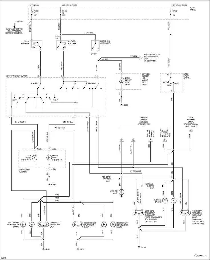
Ensure proper connections before proceeding with any electrical work related to rear illumination systems. Miswiring can lead to malfunctioning or even damage to critical components, so attention to detail is essential. To make sure everything functions correctly, follow the standard guide for connecting the circuits, which will provide clarity on the color coding and pinout configurations.
Check the power and ground circuits carefully, as these are the most crucial connections for any electrical system. Verify that all power wires are routed correctly from the fuse box, ensuring a consistent power flow to the illumination components. Always use a multimeter to confirm that there is no short-circuiting before turning the system on.
Once the power and ground connections are verified, identify the signal wires that control functions like braking, turning signals, and reverse gear illumination. These are usually distinguished by specific color codes, making them easy to identify. Proper grounding is essential for safety and the correct functioning of all related components.
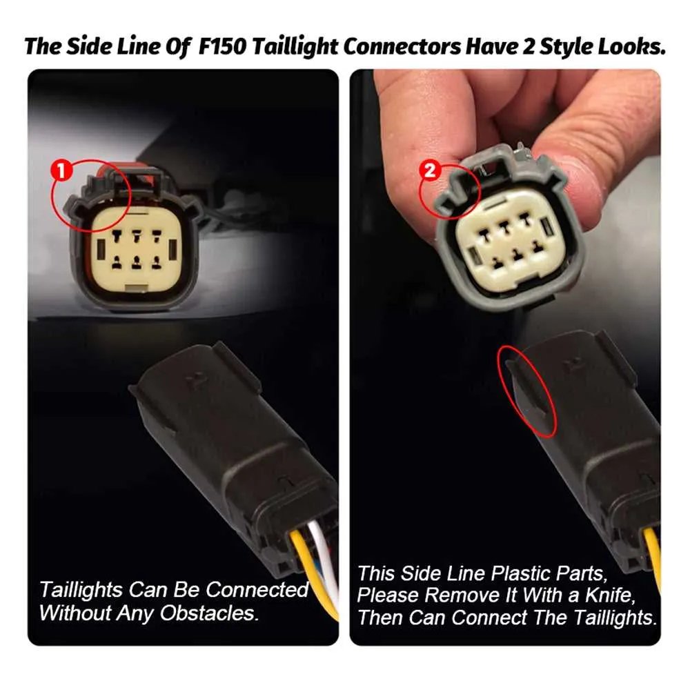
Take caution when handling connectors–over-tightening or improper handling can cause damage to the terminals. If necessary, apply dielectric grease to the connectors to ensure a strong, rust-free connection over time.
Wiring Instructions for Rear Vehicle Illumination System

To ensure proper functionality of the rear lighting system, follow these detailed steps for accurate connection and troubleshooting.
- Step 1: Begin by identifying the power source. The positive wire should connect to the vehicle’s main electrical panel. This is typically marked in red or with a solid color to denote the live current.
- Step 2: Connect the ground wire to a secure metal part of the vehicle. Use a metal-to-metal connection to prevent faulty grounding, which can affect the circuit’s performance.
- Step 3: The signal wires, often used for braking or turn indicators, should be routed separately from power wires to avoid interference.
For effective installation:
- Ensure that the connectors are tightly secured to avoid loose connections that may cause malfunction.
- Test all functions (brakes, reverse, signals) before final installation to confirm proper signal transmission.
If there is no response from a light after installation, check the following:
- Inspect the fuse linked to the system. If blown, replace it with an appropriate fuse based on the vehicle’s specifications.
- Verify that the wiring connections are free from corrosion or wear.
- Ensure the bulbs are correctly installed and functional.
Understanding the Electrical Connections for Rear Illumination Units
Start by identifying the positive and negative terminals for the rear illumination system. The positive wire typically carries current from the vehicle’s main power source, while the negative wire serves as the return path to the grounding point. Always use a multimeter to verify continuity and ensure proper grounding to avoid short circuits or improper functioning.
The brake signal should be routed to the appropriate circuit, allowing for an increase in intensity when the brake pedal is engaged. A dedicated wire from the vehicle’s braking system activates this signal. When connecting, make sure the wire gauge matches the recommended size to prevent overheating or voltage drop.
For turn signals, a separate connection is required. Ensure the wire for the turn indicator is correctly spliced into the vehicle’s directional system. It’s essential to test the polarity to confirm correct operation, as reversing the connections can cause malfunctioning or indicator errors.
Ensure all connections are securely tightened using crimp connectors or soldering to prevent loose contacts. Corroded or weak connections often lead to erratic behavior, so inspect the connection points regularly for signs of wear or degradation.
Finally, check the fuse for the circuit. If the illumination units aren’t functioning as expected, inspect the fuse box for any blown fuses or damage. Replace with the proper amperage fuse to ensure safety and functionality.
Troubleshooting and Repairing Rear Lamp Electrical Issues

First, check the fuse for the corresponding circuit. If the fuse is blown, replace it with one of the same amperage. A blown fuse can often indicate an underlying issue, such as a short or faulty connection, that should also be addressed.
Next, inspect the connectors at the lamp assembly. Ensure they are clean and free of corrosion. Use electrical contact cleaner to remove any dirt or oxidation that might disrupt the flow of current. If connectors appear damaged, replace them or clean them thoroughly with a wire brush.
If the issue persists, test the circuit for continuity using a multimeter. Place one probe on the positive terminal and the other on the ground. A lack of continuity suggests a break in the circuit that requires repair. Check for any visible damage to the wires, including signs of wear, fraying, or melting.
For damaged wires, carefully strip the insulation back and use wire nuts or electrical tape to connect the broken sections. Ensure the connection is tight and insulated to prevent any further damage. If the wire is too damaged or corroded, it may need to be replaced entirely.
Finally, check the lamp assembly itself. If the internal components are burnt out or malfunctioning, consider replacing the entire unit to restore proper functionality.
Step-by-Step Guide to Replacing the Rear Illumination Circuit Harness
1. Prepare Your Tools: Gather necessary equipment: a socket wrench set, electrical tape, and a new harness assembly designed for the vehicle’s model. Ensure you have appropriate replacement parts for the specific system.
2. Disconnect the Power Supply: Always begin by detaching the vehicle’s battery. This ensures safety while working with electrical components and prevents any accidental short circuits.
3. Access the Area: Remove the protective covers or panels around the rear section. This may involve loosening screws or clips holding the trim in place. Ensure the area is clean and free of debris before proceeding.
4. Detach the Existing Harness: Locate the connector points for the existing assembly. Gently pull apart the connectors without damaging the terminal contacts. If the harness is secured with clips, use a flat tool to disengage them without causing breakage.
5. Install the New Harness: Position the new wiring assembly in place, following the same path as the old one. Carefully attach the connectors to their corresponding terminals. Double-check alignment to ensure proper contact between the wires and connectors.
6. Secure the Wiring: Use electrical tape or clips to fasten the wiring in place. Ensure the wires are not pinched and have enough slack to avoid tension when the vehicle moves. Position the wires in a way that avoids any contact with hot surfaces or moving parts.
7. Test the Functionality: Before reassembling any trim or panels, reconnect the battery and test the newly installed system. Verify that all functions, such as signal indicators and brake activation, are working as expected.
8. Reassemble and Finish: Once the new wiring is tested and confirmed to be functioning, reattach any covers, panels, or trim pieces removed during the process. Ensure everything is securely in place.