To ensure optimal engine performance, it’s crucial to know how the components of the fuel system are connected and operate. Identifying each part’s function in a high-performance engine can prevent common issues related to fuel delivery and efficiency. For engines with a 6-cylinder setup, the integration of fuel injectors, pumps, and associated connectors plays a key role in smooth operation.
First, focus on the primary pump and injector positioning. Proper routing of the delivery pipes is vital to maintain the right pressure levels. In systems where precision is paramount, like on heavy-duty machinery, understanding the flow from the tank to the injectors will help in diagnosing leaks or clogs that could hinder performance.
Next, pay close attention to the return system. The excess fuel that doesn’t get injected must safely return to the tank, and a clogged or faulty return line could lead to significant operational problems. Keep track of the connections, ensuring they are tight and corrosion-free to prevent loss of fuel and pressure fluctuations.
For those working on mechanical repair or upgrades, consulting the exact path the liquid follows from one part to another will ensure you avoid common errors. A clear understanding of the entire route, including key attachment points and clamps, is essential for any diagnostic procedure or replacement task.
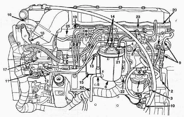
Fuel System Schematic for 24v 5.9L Engine
Ensure proper routing of high-pressure plumbing to avoid fuel system issues. Start by verifying the main feed pipe from the tank to the primary pump. The inlet should be checked for any blockages that might cause fuel starvation. Make sure the connectors are tight and free from corrosion to maintain optimal performance.
The return system, which carries excess from the injectors, must be unobstructed. It’s crucial to monitor the return lines for leaks or cracks as these can lead to pressure loss and potential fuel wastage.
Inspect the injector rail for any signs of wear or fuel seepage. Use high-quality seals when replacing any components to prevent air ingress, which can cause poor engine performance.
Check the pressure relief valve; its role is critical in maintaining system balance. If this component malfunctions, it can lead to significant issues with fuel delivery under load.
Finally, clean the fuel filter regularly. A clogged filter can cause pressure build-up and affect injector efficiency, leading to engine misfires or reduced power output.
Understanding the Routing of the Injection System for the 6BT Engine

To ensure optimal performance, it is crucial to follow the correct routing of the system that delivers fuel to the injectors. Here are key points for routing this system properly:
- Start by confirming the position of the supply pump. It should be securely mounted and aligned with the engine’s inlet points.
- Ensure the primary delivery tube from the tank flows seamlessly into the inlet of the fuel filter. The filter should be clean and not clogged.
- The connections to the rail need to be leak-free. Check for any loose or worn fittings.
- Properly secure the injectors with the correct hoses to prevent vibrations from causing wear on the seals.
- Verify that the return lines are installed in a way that allows excess to flow back into the tank without resistance. These should not be pinched or blocked.
- Check the overall layout to minimize sharp bends, which could restrict the flow of diesel.
Periodic inspections of the connections and tubes will avoid failures during high-load conditions. Also, replace any components that show signs of wear to prevent larger issues down the road.
Identifying Key System Components in the Schematic

Begin by locating the primary components that control the flow of the liquid to the engine. These typically include the main pump, filters, injectors, and high-pressure tubes. The pump is often situated near the start of the circuit, drawing from the tank and pressurizing the liquid. The filter follows, ensuring contaminants are removed before the liquid reaches sensitive components.
Next, identify the injectors, which are responsible for delivering the liquid into the combustion chamber under high pressure. These are generally represented by small, cylindrical icons on the schematic. High-pressure hoses or tubes connecting the pump to the injectors should be noted for any potential leakage points.
Ensure the connections between components are depicted with clear lines, often showing direction of flow. Look for any valves or regulators that may control pressure or volume at various points in the system. These are critical for maintaining optimal performance and preventing system overload.
Don’t overlook the return lines, which allow unused liquid to be cycled back to the tank. The return path is often shown separately, ensuring that excess is handled properly without affecting overall performance.
Lastly, take note of any electronic sensors and control units that regulate the operation of the system. These components are crucial for real-time adjustments based on engine needs and conditions.
Common Fuel System Issues and Troubleshooting
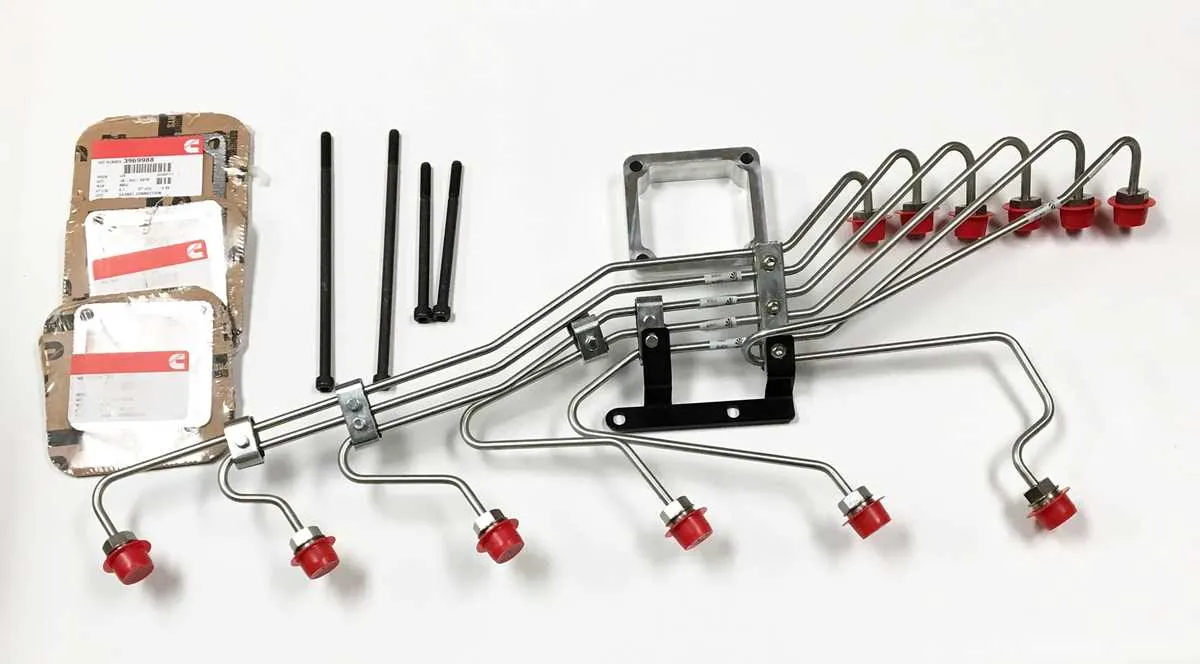
If you’re experiencing irregular engine performance, start by inspecting the injector supply pipes for cracks or leaks. These can lead to air entering the system, causing misfires or poor combustion. Tighten any loose connections, especially around the fuel filter assembly and the high-pressure side of the injectors.
Low pressure or erratic pressure readings often result from a damaged fuel pump or clogged filter. Replace any clogged filters immediately. For pumps, verify the pressure with a gauge and replace if readings fall outside the manufacturer’s specifications.
Weak or inconsistent starting could be due to a blocked or corroded return line. Ensure that the return system is clear and free from debris. Check for corrosion or wear around connectors, particularly where the return line meets the tank or pump.
If you’re noticing fuel smell or pooling around connections, inspect the seals and gaskets around the injector area and pump. These seals degrade over time, leading to leaks. Replacing damaged seals is critical to prevent further damage to components and avoid pressure loss.
Air in the system may cause rough idling or stalling. Bleed the system to remove air by following the recommended purge process. If bleeding doesn’t resolve the issue, the problem could lie in the pump or its check valves, which may need replacement.
Excessive smoke or incomplete combustion can indicate an issue with the supply pipes, leading to improper fuel delivery to the injectors. Inspect each line for cracks, clogs, or kinks that might impede flow.