Understanding the structure of your watercraft is crucial for effective maintenance and repairs. Familiarize yourself with each component’s position and function within the system to streamline troubleshooting and part replacement. Accurate identification of individual elements ensures that no critical part is overlooked during servicing.
Referencing the correct schematics is key when attempting to fix or replace any damaged element. Diagrams offer a clear, visual representation of how each piece fits into the larger assembly, helping you to navigate complex repair tasks with precision. These detailed visuals also assist in sourcing the right components, avoiding the confusion of ordering incorrect or incompatible items.
Organizing your tools and supplies according to the component categories is an effective strategy. Start by breaking down the structure into manageable sections, such as propulsion, steering, and electrical systems. By segmenting tasks and focusing on one area at a time, you ensure that the process remains efficient and that you don’t miss any steps during repairs.
Additionally, having access to official technical manuals can save a lot of time when looking for specifications and part numbers. These resources provide insights into factory-approved configurations, making it easier to find the exact replacements needed.
Understanding the Exploded View for Personal Watercraft Components

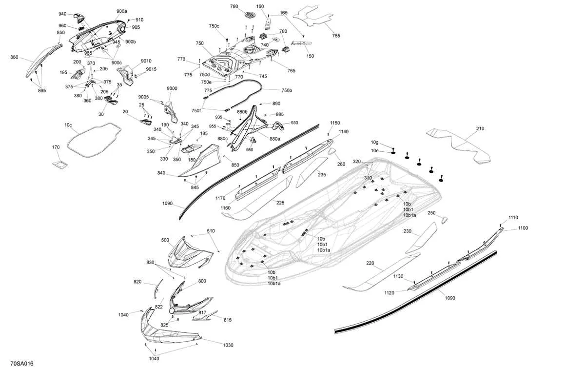
For proper maintenance or repair, it’s crucial to familiarize yourself with the exploded view for your watercraft model. This detailed schematic provides a comprehensive breakdown of the components and their placements. Start by identifying the major sections: engine, propulsion system, and steering mechanism. Each segment is marked clearly, allowing you to pinpoint any part that may require replacement or adjustment.
Engine Assembly: Focus on the motor unit first. Examine the location of the pistons, bearings, and fuel system. An exploded view helps you identify the specific parts in the powertrain and how they interact. This can prevent unnecessary disassembly when troubleshooting power issues.
Drive System: The view for the drive system highlights key elements like the impeller, shaft, and couplings. Pay attention to the alignment of these parts, as incorrect positioning can lead to decreased performance or even damage. An accurate schematic ensures that each component fits together securely and functions optimally.
Steering Components: For easy identification of steering-related issues, carefully inspect the layout of the handlebars, cables, and linkages. Knowing the arrangement helps in diagnosing steering problems or replacing worn-out parts. Look for wear indicators on rubber seals or joints that might not be immediately visible without a clear representation.
Accessing and Using Schematics: Always refer to the specific model’s exploded view when sourcing replacements. Manufacturers often provide these illustrations in user manuals or online resources. Utilize them to cross-reference part numbers and specifications to ensure compatibility with your craft.
By understanding the layout and function of each section, you can streamline the repair or maintenance process, ensuring smooth operation and longevity of your personal watercraft.
Understanding the Key Components of a Watercraft’s Assembly Layout

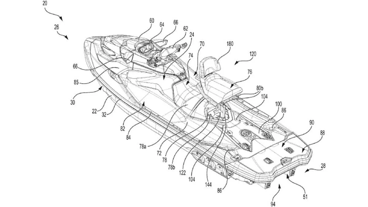
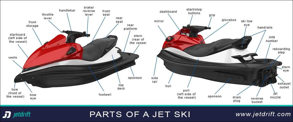
To properly maintain and repair a water vehicle, it’s crucial to understand the assembly layout of its components. Below are the most significant areas that should be carefully examined when working with the schematic of such a craft:
- Engine Section: This includes the motor unit, spark plugs, fuel lines, and cooling systems. Pay special attention to the arrangement of fuel and exhaust components.
- Steering and Control Mechanisms: Steering cables, handlebars, and throttle control units are essential for maneuverability. Their connection points must be precise to ensure smooth handling.
- Hull and Structural Framework: Check for the location and configuration of braces, reinforcements, and joints that maintain the integrity of the vessel’s structure. These are critical for safety and performance.
- Electrical System: Components such as wiring, fuse boxes, battery, and electrical connectors must be inspected regularly for corrosion or wear. Proper connection and placement are key to functionality.
- Drive Mechanism: The drive shaft, impeller, and related components are integral for propulsion. Ensure proper alignment and that all parts are securely fastened to prevent malfunction.
- Fuel System: Fuel tank, filters, and lines are crucial for smooth operation. Regular checks for leaks and cleanliness help maintain engine efficiency.
- Safety and Auxiliary Components: This section involves the exhaust, emergency shut-off switches, and flotation devices. Correct installation and accessibility of these elements can prevent accidents.
When reviewing these areas, always refer to the specific layout for that model to avoid mistakes. Each assembly can vary slightly based on design revisions, so ensure you are consulting the correct guide for your specific machine.
How to Read and Interpret Watercraft Component Schematics for Repairs
Start by identifying the specific model and year of your watercraft. This is essential, as designs and configurations can differ significantly between models and production years. Once you have the correct reference, proceed to locate the schematic section that corresponds to the system you’re working on–whether it’s the engine, steering, or exhaust system.
Examine the numbers and part labels carefully. Each part is assigned a unique code or reference number. These identifiers are crucial for ordering the right components. Use the schematic as a map, where the numbers and visual indicators directly correlate to the physical components.
Note the part groupings: Most schematics are divided into sections based on functionality (such as fuel, electrical, or mechanical systems). Pay attention to these divisions to quickly navigate to the area of interest. Within these groups, parts are typically listed in assembly order, showing the sequence in which they should be installed or removed.
Pay attention to orientation: Some components, especially seals or gaskets, may be directional. The schematic will often indicate which side of the part should face outward or inward. This ensures proper installation and prevents leaks or misalignment.
In case of assembly instructions, verify that the parts are shown in the exact position relative to one another. If you’re troubleshooting a malfunction, look for connections, such as hoses or electrical wiring, that could be contributing to the issue. Cross-reference these with your maintenance manual for additional specifics on installation or replacement procedures.
Color coding and symbols can also be helpful. Some schematics use colors or special symbols to differentiate between various types of materials (metal, plastic, rubber) or highlight specific functions (such as pressure or temperature monitoring). Pay attention to these cues when interpreting the chart.
Lastly, double-check with your dealer or manufacturer for any updates to the parts list. Over time, revisions may occur that affect part compatibility. Keeping this in mind will help avoid errors when replacing components.
Common Issues Identified in Watercraft Component Schematics and Their Solutions

If you encounter difficulties while interpreting component layouts for your personal watercraft, the most common issues typically stem from incomplete or unclear labeling, misplaced parts, and difficulty matching part numbers to specific models. To address these challenges:
1. Always ensure that the schematics you’re using are up-to-date. Manufacturers frequently update parts to improve performance or correct previous errors. Cross-check part numbers with the model year and specific engine type.
2. Look for components that appear in multiple locations but are marked differently. This often happens with assemblies where parts are interchanged depending on the engine or configuration. In such cases, refer to detailed service manuals or consult with a professional to confirm part compatibility.
3. Pay close attention to exploded views. Inaccurate or poorly detailed views can lead to confusion about how parts fit together. When in doubt, contact the manufacturer for a more detailed or clearer schematic.
4. Be mindful of part compatibility across different model ranges. Some components may look identical but serve different functions across various models. If you’re unsure, verify through the part’s description or consult with a dealership for guidance on model-specific needs.
5. For issues related to assembly order or missing connections, refer to exploded assembly diagrams that detail how subcomponents fit together. These often provide a clearer view than isolated part lists, especially for complex systems like the electrical or fuel systems.
6. If you’re unsure about part identification, use a part finder tool on the manufacturer’s website or third-party supplier resources to ensure that you’re selecting the correct component for your needs.