
Brake motors play a crucial role in various industries, where safety and precision are of paramount importance. These motors are equipped with an integrated braking system that ensures immediate stopping of the motor shaft when power is cut off. The wiring diagram of a 3 phase brake motor is essential for understanding the connections and ensuring proper installation.
In a 3 phase brake motor, there are three windings – A, B, and C. Each winding is connected to a separate phase of the power supply, forming a balanced and efficient electrical system. The wiring diagram illustrates the correct arrangement of the connections, allowing for smooth and controlled brake operation.
When it comes to wiring a 3 phase brake motor, it is crucial to follow the manufacturer’s instructions and adhere to safety standards. The wiring diagram typically includes details such as the numbering of the winding terminals, correct phase sequence, and connection points for the brake mechanism. This information ensures that the motor functions optimally and the braking system engages reliably when needed.
What is a 3 Phase Brake Motor?
A 3 phase brake motor is a type of electric motor that is specifically designed to incorporate a mechanical brake system. This type of motor is commonly used in industrial applications where precise stopping and holding of the load is required.
The brake system of a 3 phase brake motor works by applying an electrically controlled brake disc or drum to the motor shaft. When power is applied to the motor, it rotates and generates torque to drive the load. However, when power is cut off or a stop command is given, the brake system engages and stops the motor shaft from rotating, holding it in a fixed position.
This braking mechanism provides several advantages in industrial applications. Firstly, it ensures the safety of workers by quickly and effectively stopping the motor and preventing any unintended movements or accidents. Secondly, it allows for more accurate positioning of the load, as the motor can be stopped at exactly the desired position. Finally, it reduces wear and tear on the motor and other components, as the brake system absorbs the stopping force instead of relying solely on the motor to decelerate the load.
Overall, a 3 phase brake motor is an essential component in various industrial machines and equipment, providing reliable and precise stopping and holding capabilities for improved safety and efficiency.
Understanding the Basics
When it comes to wiring a 3-phase brake motor, it’s important to have a good understanding of the basics. A 3-phase brake motor is a type of motor that has three power supply lines and is equipped with a braking system to help bring the motor to a stop quickly and efficiently.
One of the key components in the wiring diagram of a 3-phase brake motor is the connection of the three power supply lines. These lines, often referred to as ‘phases,’ are labeled as L1, L2, and L3. It’s crucial to correctly identify and connect these phases to ensure the motor operates correctly.
Another important element in the wiring diagram is the connection of the braking system. The brake is typically activated by a separate power supply and is used to stop the motor quickly, which is particularly useful in applications where precision control is required or in emergency situations. It’s essential to follow the wiring diagram carefully to ensure the brake is connected correctly and functions as intended.
Additionally, the wiring diagram may also include other components such as overload protection devices or auxiliary contacts. These components ensure the motor is protected from overheating and provide additional functionality, such as signaling when the motor is running or when specific conditions are met.
In summary, understanding the basics of wiring a 3-phase brake motor is essential for ensuring proper operation and safety. Familiarizing oneself with the different power supply phases, correctly connecting the braking system, and incorporating any additional components as specified in the wiring diagram are all crucial steps in the process.
Components of a 3 Phase Brake Motor
A 3 phase brake motor is a motor that is designed with a built-in brake system. This brake system allows the motor to quickly stop or hold a load in place when power is removed. A brake motor is commonly used in applications that require frequent starting and stopping, precise positioning, or holding of a load.
The main components of a 3 phase brake motor include:
- Motor: The motor itself is the main component of a 3 phase brake motor. It consists of a stator (stationary part) and a rotor (rotating part). The stator is the outer part of the motor that generates a rotating magnetic field, while the rotor is the inner part of the motor that rotates in response to the magnetic field.
- Brake: The brake system is an essential component of a 3 phase brake motor. It is typically an electromagnetic brake that is mounted on the non-drive end of the motor, opposite the shaft. When power is applied to the brake, it releases the brake disc or drum, allowing the motor to rotate. When power is removed, the brake engages, stopping the motor or holding it in place.
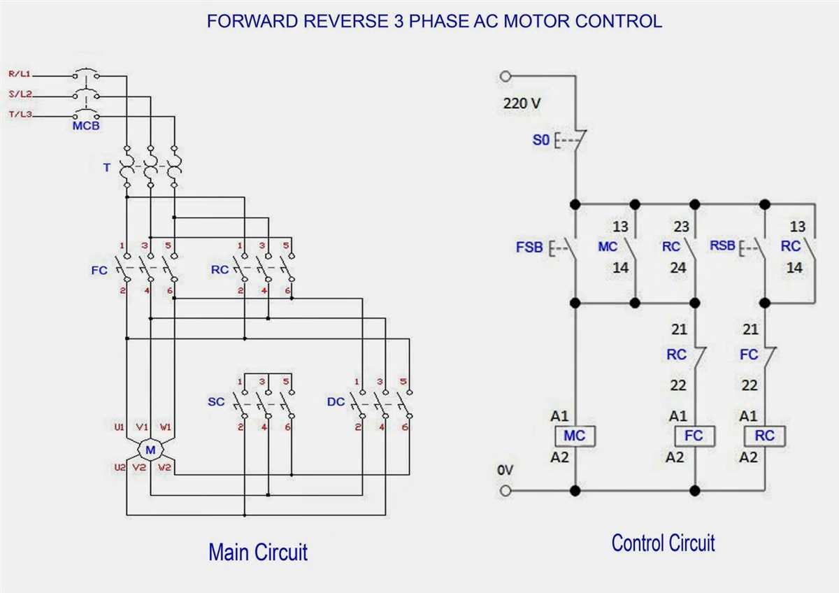
- Control Circuit: The control circuit is responsible for managing the operation of the brake motor. It includes components such as relays, contactors, and switches that control the flow of electrical power to the motor and brake. The control circuit is typically connected to an external control panel or system.
- Power Supply: A 3 phase brake motor requires a 3 phase power supply to operate. The power supply provides the necessary electrical energy to the motor and control circuit. It typically consists of three separate power lines that supply the motor with alternating current.
- Mounting Bracket: The mounting bracket is used to secure the motor and brake system to a frame or structure. It ensures that the motor remains stable and properly aligned during operation.
In summary, a 3 phase brake motor consists of a motor, brake system, control circuit, power supply, and mounting bracket. These components work together to provide precise control and stopping capability in applications that require frequent starting and stopping or holding of a load.
Wiring Diagram for a 3 Phase Brake Motor
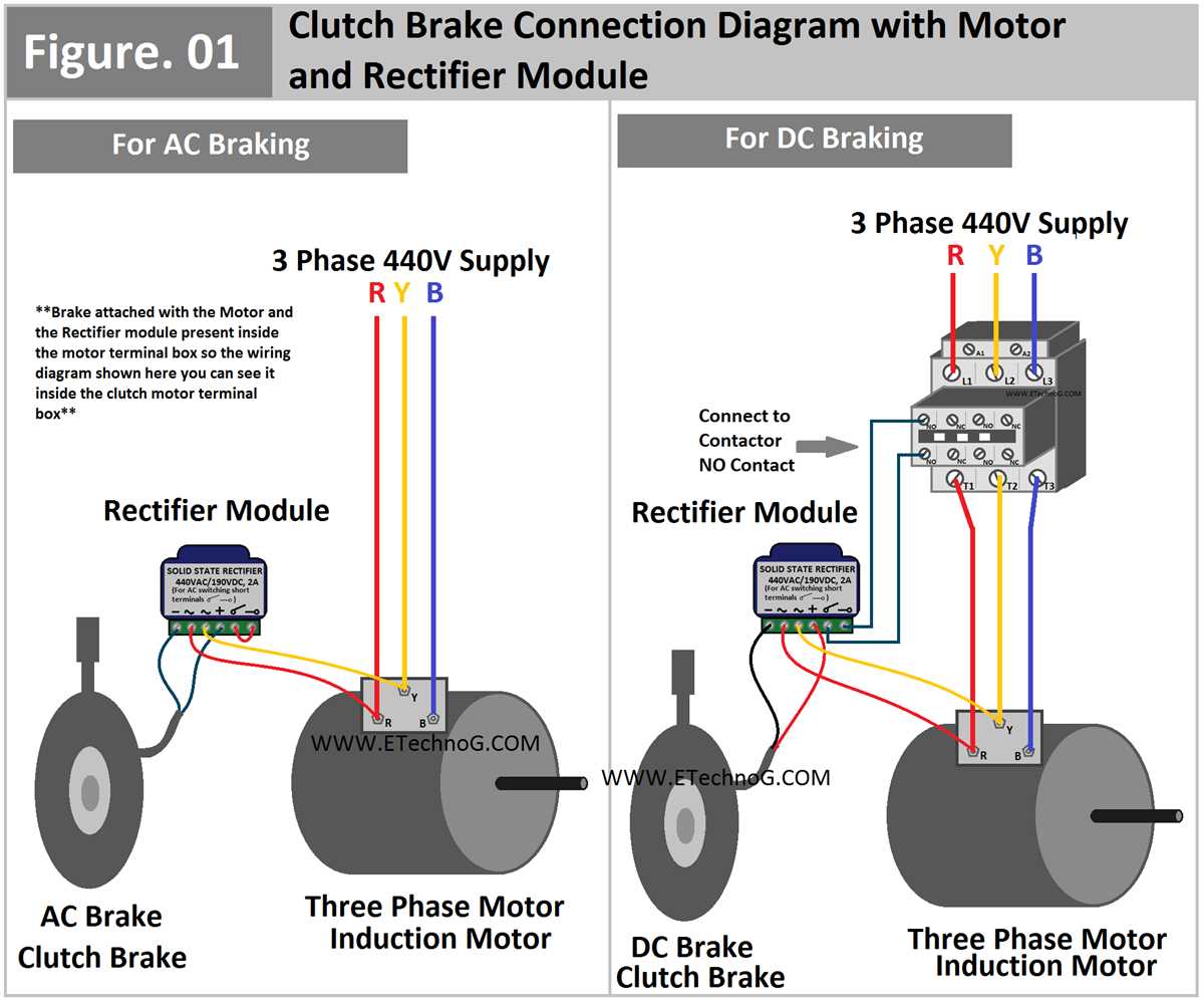
A three-phase brake motor is a type of electric motor that is equipped with a built-in brake mechanism. This brake allows the motor to rapidly stop the rotation of the shaft when power is cut off. The wiring diagram for a three-phase brake motor includes connections for the motor, brake, and control circuitry.
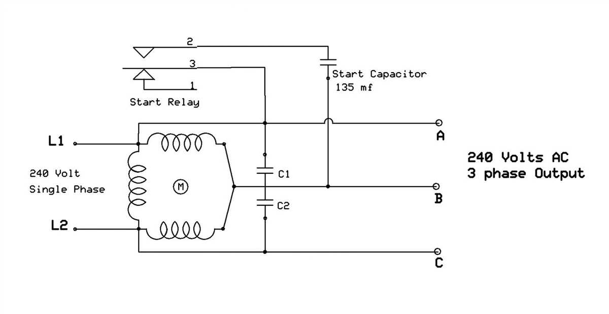
To wire a three-phase brake motor, you will need to identify the main power supply lines, the motor leads, and the brake leads. The main power supply lines are typically labeled L1, L2, and L3. These lines deliver the three-phase AC power to the motor. The motor leads are labeled U, V, and W and are connected to the motor windings.
The brake leads are labeled A+ and A-. These leads connect to the brake coil within the motor and control the engagement and disengagement of the brake mechanism. The control circuitry includes a contactor and a control switch. The contactor controls the flow of power to the motor and brake, while the control switch allows the operator to start and stop the motor.
Wiring Diagram:
- Connect L1, L2, and L3 to the power supply.
- Connect U, V, and W to the motor windings.
- Connect A+ and A- to the brake coil.
- Connect the control switch to the control circuitry.
- Connect the control circuitry to the contactor.
| Motor Connections | Brake Connections | Control Circuitry |
|---|---|---|
| L1, L2, L3 | A+, A- | Contact or switch |
| U, V, W | Brake coil |
It is important to follow the wiring diagram carefully to ensure proper installation and operation of the three-phase brake motor. Improper wiring can lead to motor or brake failure, as well as potential safety hazards. If you are unsure about the wiring or installation process, it is recommended to consult a professional electrician or refer to the motor’s instruction manual.
Step-by-Step Guide: 3 Phase Brake Motor Wiring Diagram
In this step-by-step guide, we will walk you through the process of wiring a 3 phase brake motor. This diagram is applicable for various industrial applications where a motor needs to be stopped quickly using an electromagnetic brake.
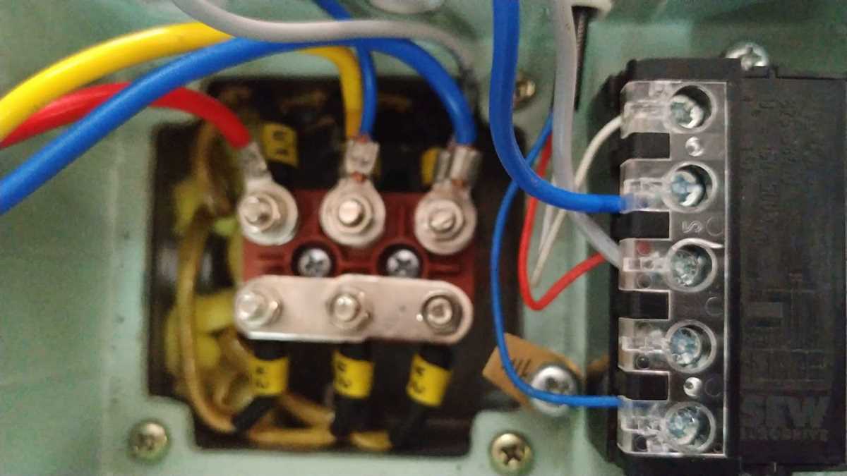
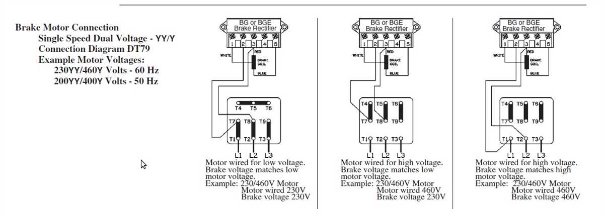
Step 1: Identify the motor terminals
The first step in wiring a 3 phase brake motor is to identify the motor terminals. Typically, a 3 phase motor will have six terminals labeled U1, V1, W1 for the primary winding, and U2, V2, W2 for the secondary winding. Additionally, there may be two terminals labeled A1 and A2 for the electromagnetic brake.
Step 2: Connect the primary winding
Next, you will need to connect the three terminals U1, V1, W1 of the primary winding to the corresponding phase terminals of the power supply. Make sure to use suitable connectors and ensure proper insulation.
Step 3: Connect the secondary winding
Similarly, connect the three terminals U2, V2, W2 of the secondary winding to the remaining corresponding phase terminals of the power supply. Again, ensure proper insulation and use suitable connectors.
Step 4: Wiring the electromagnetic brake
Now, it’s time to wire the electromagnetic brake. Connect the terminals A1 and A2 to the control circuit for the brake. The control circuit will typically include a power source, a switch, and a relay or contactor.
Step 5: Test the wiring
Once all the connections are made, it is important to test the wiring to ensure everything is functioning correctly. Apply power to the motor and verify that the motor starts and stops smoothly when the brake is engaged and disengaged.
Following this step-by-step guide will help you correctly wire a 3 phase brake motor. Make sure to refer to the manufacturer’s wiring diagram and consult a professional if you are unsure about any step in the process.
Common Troubleshooting Issues
When working with 3 phase brake motors, there are some common troubleshooting issues that may arise. These issues can often be resolved by following a few simple steps. Here are some of the most common issues and their solutions:
1. Motor not starting or running consistently
If the motor is not starting or running consistently, there may be a problem with the power supply. Check the voltage and ensure it is within the recommended range for the motor. Also, check the motor wiring connections to ensure they are secure and properly connected. If the wiring connections are correct and the voltage is within range, there may be an issue with the motor itself. In this case, it is recommended to consult a professional for further diagnosis and repairs.
2. Motor overheating
If the motor is overheating, there may be several potential causes. Check to make sure the motor is properly ventilated and that there are no obstructions blocking the airflow. If the motor is properly ventilated and the issue persists, it may be due to excessive load or incorrect voltage. Ensure that the motor is not being overloaded and that the voltage is within the recommended range. If the issue continues, it is best to consult a professional for further assistance.
3. Unusual noise or vibration
If the motor is making unusual noise or experiencing excessive vibration, it may be due to misalignment or worn-out bearings. Inspect the motor for any signs of misalignment or damage to the bearings. If misalignment is detected, make necessary adjustments to align the motor properly. If bearings are worn-out, they should be replaced. It is important to address any noise or vibration issues promptly to prevent further damage to the motor.
Summary

Working with 3 phase brake motors may occasionally present troubleshooting issues. However, many of these issues can be resolved by checking the power supply, ensuring proper ventilation and alignment, and addressing any excessive load or voltage issues. If the troubleshooting steps do not resolve the problem, it is recommended to seek professional assistance to avoid further damage to the motor.