
Controller Area Network (CAN) bus is a communication protocol used in automotive and industrial applications to connect various electronic control units (ECUs) and devices. It allows for the exchange of information between different systems, enabling seamless integration and functionality. To ensure compatibility and reliability, there are specific wiring standards that need to be followed when implementing a CAN bus system.
CAN Bus Topology:
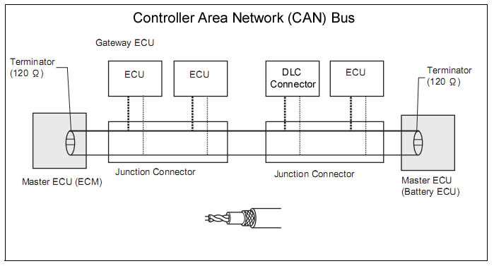
The physical layout of a CAN bus system follows a linear topology, where multiple devices are connected via a two-wire bus. The two wires are called CAN High (CANH) and CAN Low (CANL). The CANH wire carries the dominant bit (logic 0), while the CANL wire carries the recessive bit (logic 1).
CAN Bus Wiring:
When implementing a CAN bus system, it is important to follow the wiring standards to ensure proper communication and signal integrity:
- Twisted Pair: CAN bus wires should be twisted to minimize electromagnetic interference (EMI) and signal degradation. Twisting the wires helps reduce crosstalk and improves noise immunity.
- Termination Resistors: Each end of the CAN bus should have a termination resistor to prevent reflections and ensure signal integrity. The resistor value is typically 120 ohms.
- Shielding: In environments with high levels of EMI, it is recommended to use shielded twisted pair cables. The shielding helps reduce interference from external sources.
- Grounding: Proper grounding is crucial for ensuring a stable reference potential for the CAN bus system. It is important to connect the CAN bus ground to a solid and low-impedance ground point.
- Separate Power and Signal Wires: To minimize noise coupling, it is recommended to keep the power and signal wires separate. This helps reduce the chances of power-related interference.
CAN Bus Connectors:
The connectors used for CAN bus wiring should provide a secure and reliable connection. Common connector types used in CAN bus systems include the Deutsch DT Series connectors and the Molex Micro-Fit 3.0 connectors. These connectors are designed to withstand harsh environmental conditions and ensure a proper electrical connection.
CAN Bus Standards:
There are several standards and protocols associated with CAN bus, such as CAN 2.0A, CAN 2.0B, CAN FD (Flexible Data Rate), and J1939 (specifically for the automotive industry). Each standard has its own specifications and requirements, but the basic wiring principles remain the same.
In conclusion, following the proper wiring standards is essential for the successful implementation of a CAN bus system. Twisted pair wiring, termination resistors, shielding, grounding, and separate power and signal wires are all crucial factors to consider. By adhering to these standards, you can ensure reliable and efficient communication between devices in a CAN bus network.
Troubleshooting Can bus wiring issues
When troubleshooting Can bus wiring issues, it is important to follow a systematic approach to identify and resolve the problems. Here are some steps you can take:
- Check the physical connections: Start by inspecting the physical connections of the Can bus wiring. Make sure all connectors are securely plugged in and that there are no loose or damaged wires. Verify that the connectors and wires are properly seated and that there are no signs of corrosion or damage.
- Test the continuity: Use a digital multimeter to test the continuity of the wires. Start at the beginning of the Can bus network and check the continuity of each wire along the network. This will help identify any breaks or short circuits in the wiring.
- Verify the power supply: Check if the Can bus network is receiving the necessary power supply. Test the voltage at different points along the network to ensure there is no significant voltage drop or fluctuation. A stable power supply is crucial for the proper functioning of the Can bus network.
- Inspect the terminators: Can bus networks require terminators at both ends to ensure proper communication. Check if the terminators are correctly installed and functioning. A missing or faulty terminator can cause communication issues in the Can bus network.
- Use diagnostic tools: Consider using diagnostic tools, such as Can bus analyzers or scanners, to pinpoint the exact location of the problem. These tools can help identify faulty nodes, incorrect wiring configurations, or other issues that may be causing problems in the Can bus network.
By following these troubleshooting steps, you can identify and resolve Can bus wiring issues effectively. Remember to document any changes or repairs made during the troubleshooting process, as this information can be valuable for future reference.