When attaching implements to a tractor, ensure the proper setup of the three-point linkage system. This mechanism is crucial for stability and efficient operation, enabling you to easily connect various attachments for tasks like plowing, tilling, or mowing.
First, identify the top link and two lower arms of the system, as these are key components that secure the attachment to the tractor. The upper arm allows for adjustment of height and depth, while the lower arms provide lateral support. The hydraulic cylinders control the raise and lower functions, giving you precise control over the attachment’s position.
Make sure to regularly inspect the components for wear and tear, especially the pins, bolts, and hydraulic connections. A properly adjusted system ensures that the implements stay level during operation, reducing wear on both the tractor and the attachment. If any part becomes loose or damaged, it can lead to uneven results or even equipment failure.
Understanding the 3-Arm Connector System
The three-arm connector system on agricultural machinery is designed to facilitate the attachment of implements to a tractor. The setup consists of three key components: two lower arms and one top arm, each serving a distinct purpose for stability and control during operation. Proper adjustment of these arms is critical for optimal performance and safety.
The lower arms provide lateral support, keeping the equipment aligned with the tractor’s path. Ensuring that these arms are at equal lengths is vital for preventing uneven wear and unnecessary strain on the equipment. The top arm controls the vertical position, allowing for lifting or lowering of the implement, thus enabling precise adjustments for different tasks.
To maintain stability and avoid damage, always check the alignment and integrity of the linkage points. If the arms are not properly calibrated, the implement may not function correctly, which could lead to operational inefficiency or even mechanical failure.
For effective operation, ensure that the arms’ attachment points are regularly lubricated to prevent rust and ensure smooth movement. This simple maintenance task can extend the life of both the tractor and attached equipment, improving overall reliability.
How to Interpret the Components of a 3-Point Attachment System

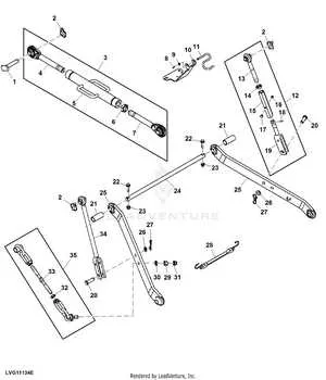
Start by identifying the key parts of the system: the top link, lower arms, and lift arms. Each component plays a specific role in connecting implements to a tractor. Understanding their function is crucial for proper use and maintenance.
First, the top link is responsible for stabilizing the attachment vertically, ensuring it remains aligned during operation. It is adjustable, allowing you to change the angle and height of the attached implement.
The lower arms serve as the primary means of lifting and lowering the implement. These components are also adjustable to accommodate different attachments. Ensuring these arms are properly aligned and secured will prevent excessive wear and uneven operation.
The lift arms control the horizontal movement of the implement. They work in tandem with the lower arms, providing the necessary force to raise or lower the attached tool smoothly.
Check the implement’s connection points as well. They are critical for ensuring a secure attachment. These points are usually reinforced with pins or bolts, which should be inspected regularly to avoid damage during heavy use.
The diagram typically indicates the relative positioning of these elements. Focus on the connections between the tractor and implement, ensuring that no part of the system is under excessive strain or improperly aligned.
| Component | Function | Adjustment |
|---|---|---|
| Top Link | Stabilizes implement vertically | Adjustable for height and angle |
| Lower Arms | Lifts and lowers implement | Adjustable for length and fit |
| Lift Arms | Controls horizontal movement | Non-adjustable in most cases |
| Connection Points | Secures implement to tractor | Check regularly for wear |
By focusing on these components and their interconnections, you can ensure that the system operates efficiently, minimizing the risk of damage or operational failure.
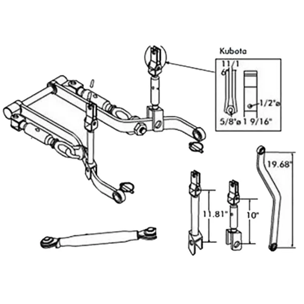
Key Measurements and Dimensions in 3-Point Attachment Design
Ensure precise alignment between the implement and the tractor for maximum performance. Key measurements include the distance between the lower links, the width of the tractor’s rear axle, and the height of the upper link attachment. Adjust these to avoid instability and improve operational efficiency.
For the lower link spacing, the typical range is between 16 and 30 inches, depending on the tractor model and the equipment in use. This measurement influences the angle of the attachment during operation and can affect the load distribution.
The upper link’s attachment height is crucial for ensuring that the equipment maintains an optimal working angle. This should be between 20 and 25 inches, as it ensures balanced force distribution when the implement is raised or lowered.
In terms of the connection points, the lower link attachment height should typically range from 10 to 14 inches from the ground. This varies based on the size and design of the tractor, but should always be kept consistent to ensure a secure fit with the implement.
For safety and reliability, maintain the center-to-center distance of the link connections at a standard of 18 to 24 inches. This helps in minimizing wear on both the tractor and attached equipment by maintaining correct load distribution during operation.
When designing or adjusting an implement, always verify that the link lengths and attachment heights align with these standards to avoid operational issues and enhance the lifespan of the machinery.
Common Issues in 3-Point Attachment Setup and How to Solve Them
Incorrect attachment height is a frequent issue. Ensure the link arms are adjusted to the proper position to avoid uneven lifting. When the tool doesn’t raise or lower correctly, inspect the lift links for misalignment or wear.
Another issue arises when the implement is not level when connected. This can be due to improper upper link adjustment. Adjust the upper link to ensure that the implement sits flat, preventing uneven wear and stress on the machine.
Common causes of poor performance:
- Damaged or worn pins and bushings that cause instability and make the implement sway.
- Incorrectly sized links that affect weight distribution.
- Contaminants in the hydraulic system, leading to slow or erratic lifting.
To address these, first, inspect all pins and replace any that show significant wear. For stability issues, ensure the link arms are properly adjusted to match the implement’s size. Hydraulic fluid should be clean and the system checked for leaks regularly.
If you notice uneven lifting forces, adjust the stabilizer bars to prevent lateral movement and ensure that both arms are lifting in sync. Additionally, double-check that all connections are tight and there are no loose bolts that can cause instability during use.
Maintaining your setup:
- Regularly clean and grease the system to reduce friction and prevent wear.
- Check the integrity of the lower arms and crossbars for any signs of bending or cracking.
- Inspect hydraulic connections for leaks and ensure fluid levels are adequate.
By following these steps, you can prevent common issues and keep your implement functioning efficiently for longer periods.