To set up multi-position circuits efficiently, follow this wiring approach for controlling lights or other appliances from multiple locations. The configuration involves using specialized control points to manipulate the flow of electricity across distinct paths, ensuring seamless operation of connected devices.
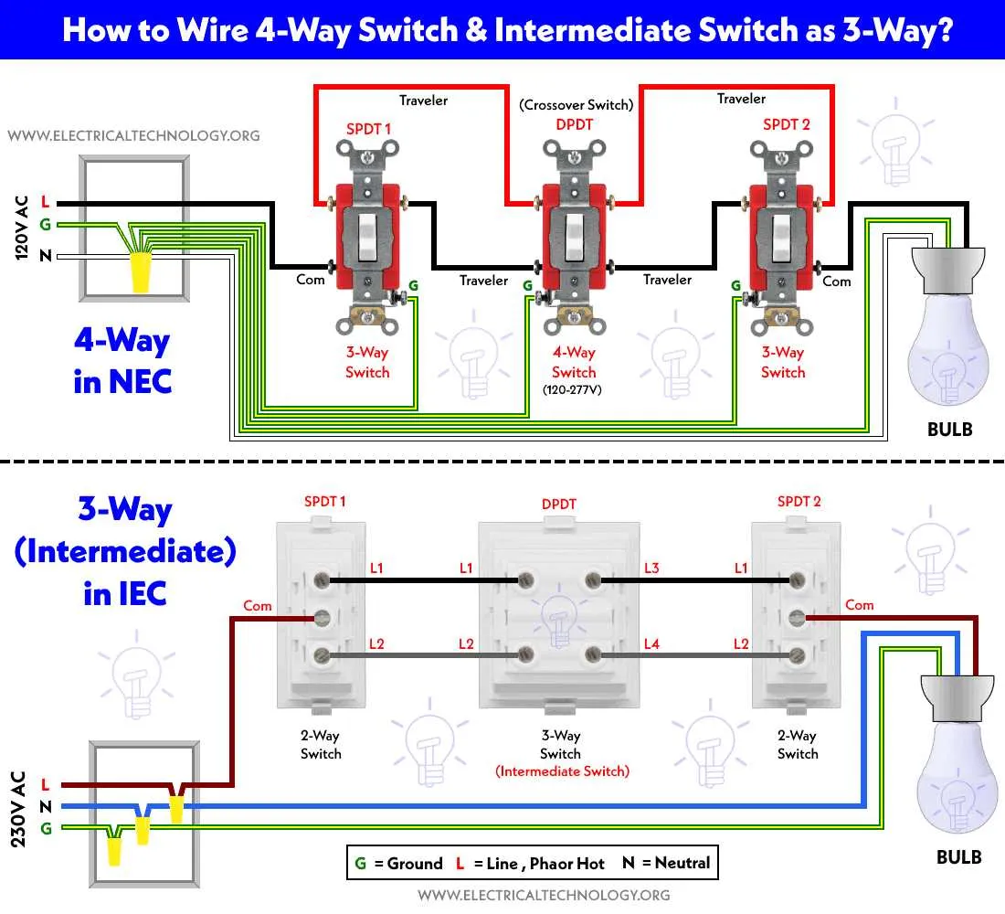
When working with the first type of setup, you need two control points and an intermediate junction. This allows the user to manage a load from two different locations, providing flexibility in controlling the circuit. The wiring follows a straightforward process that connects each control unit with the load via alternating connections.
For the second type, the complexity increases with the addition of a third control unit. This setup facilitates control from three different locations, ideal for larger spaces like hallways or staircases. The connections between each control point and the load ensure proper routing of current, allowing the user to switch the circuit’s state from multiple positions without interference.
Key steps to follow:
- Ensure that all connections are secure and insulated to prevent short circuits.
- Verify the polarity of the wiring to ensure proper flow of current.
- Use the correct gauge of wire for safety and efficiency.
Always test the system after installation to confirm proper operation before use.
Wiring for 3-position and 4-position Circuits

For proper installation of 3-position and 4-position circuits, follow these clear steps:
- 3-position circuit: Use two devices in a series connection to control one light fixture. The first device acts as a main controller, while the second allows for control from a different location.
- 4-position circuit: Includes an additional device that provides a third control point. This setup requires careful placement of each terminal to ensure smooth operation between all controllers.
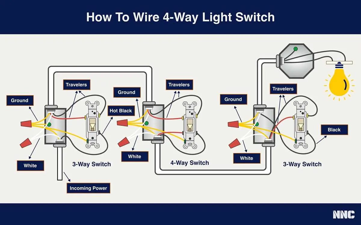
- Common wiring practices: Each device should be connected with a traveler wire that connects all the terminals properly. The hot wire connects to the common terminal on the main controller device.
Ensure connections are solid, and wire insulation is intact to avoid short circuits. Use a continuity tester to verify that all connections are made correctly before turning on the power supply.
- Check the wiring before final installation for any signs of wear or poor connection.
- Double-check polarity to avoid incorrect wiring that could damage the equipment.
- If unsure about specific connections, refer to your product’s manual or hire a professional electrician to avoid mishaps.
Understanding the Wiring for a 3-Wire Circuit
For proper installation of a three-wire circuit, follow this specific configuration: two traveler wires should connect both devices, with the common terminal of each being wired to the power source and load respectively. The neutral wire will complete the circuit. Ensure that all connections are securely tightened to avoid short circuits.
At the first device, connect the incoming power to the common terminal. The traveler terminals will be linked to the corresponding traveler wires running between both devices. At the second device, connect the load to the common terminal and attach the remaining traveler wires to their corresponding terminals.
Key Considerations: Use proper gauge wiring for safety. The neutral wire, which does not carry current in this setup, should always return to the power panel, while the live wires (traveler and common) should be correctly identified for easy troubleshooting.
Connecting a 4-Point Control for Multiple Locations

To set up a 4-point control system for a light from different locations, use two standard 3-point controllers and a specialized controller in between. Connect the common terminal of the first 3-point device to the power source. The traveler wires will then link it to the second 3-point controller, which will be connected to the light fixture. Finally, the last device in the sequence will allow the user to toggle the light on or off from multiple points.
Ensure that the common terminal on each of the intermediate devices is linked to the traveler wire, and that all three devices share the same neutral connection. This arrangement ensures seamless control from different locations without causing electrical interference or malfunction. Proper grounding should be maintained for safety at each installation point.
When wiring, it’s crucial to double-check the connections, as errors can result in malfunction. Keep a tester to verify the functionality before finalizing the setup. Proper labeling of wires will help prevent confusion during maintenance or future adjustments.
Common Wiring Errors and How to Avoid Them
Ensure that the power is turned off before starting any electrical work to prevent accidents. Incorrectly connecting wires to the wrong terminals is one of the most frequent mistakes. Always verify the correct configuration of each wire, referencing the specific instructions for each device.
Another common issue is improper grounding. Neglecting to properly ground the system can lead to potential electrical hazards. Double-check the ground wire connection to ensure it is securely attached to the appropriate terminal.
When connecting multiple circuits, avoid overloading a single connection point. This can cause overheating and potential failure of the system. Distribute the load evenly across the connections to ensure reliable performance.
Incorrectly wiring the traveler terminals can cause functionality issues, such as failure to operate the circuits correctly. Take extra care to identify and properly connect each traveler wire based on the installation manual to avoid this error.
Lastly, misidentifying the common terminal can lead to malfunction. Ensure that the correct wire is connected to the common terminal, as this is crucial for proper operation. Use a tester to confirm connections are accurate before finalizing the installation.