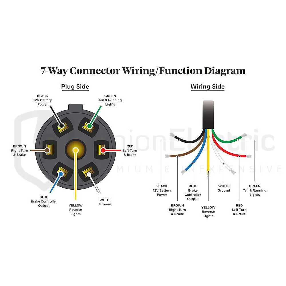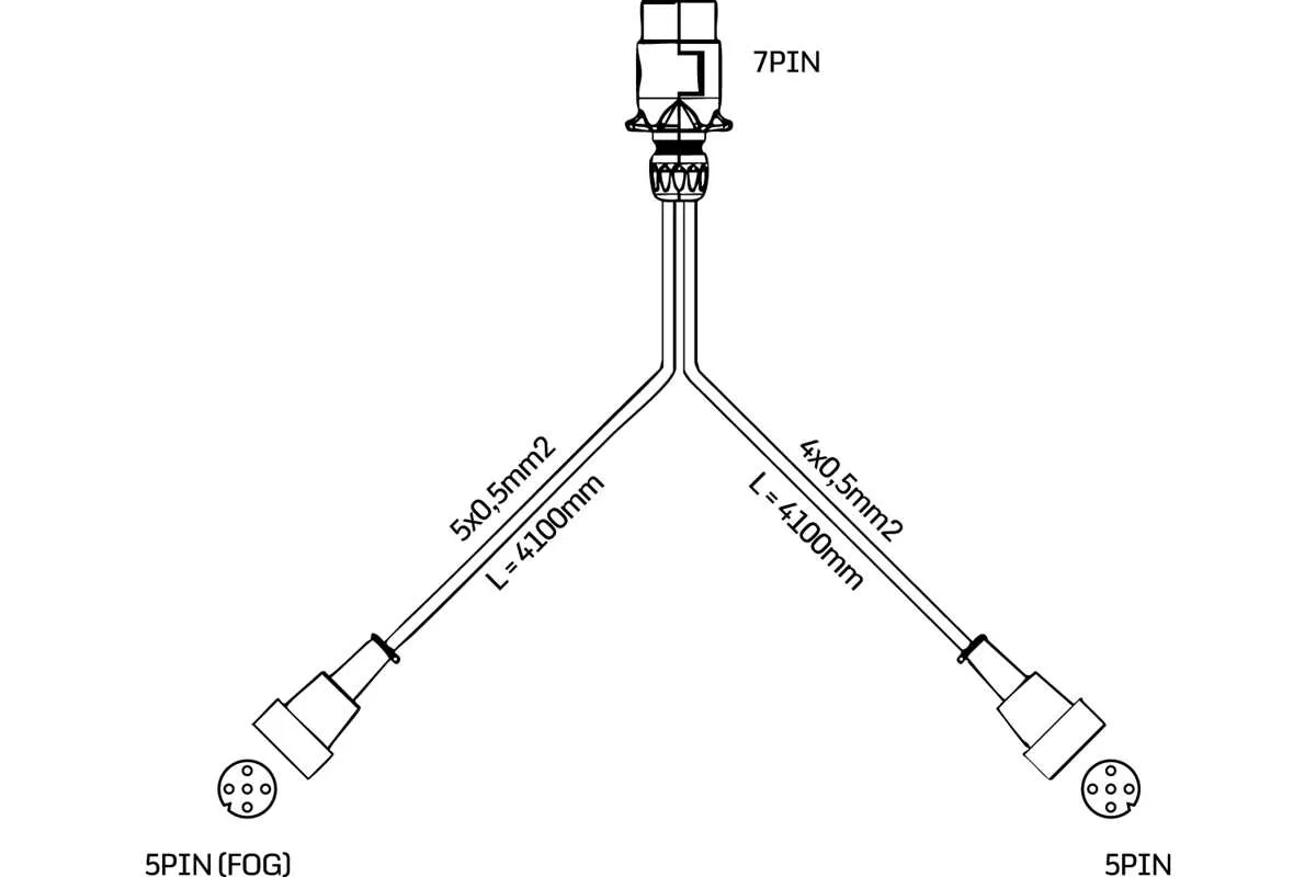
Ensure correct wiring of the 7-terminal plug by following standardized color codes and terminal assignments. Each contact serves a specific function such as tail lights, brake lights, reverse signal, and ground connection. Miswiring can cause malfunction or safety hazards during towing operations.
The typical layout includes separate terminals for indicators, auxiliary power, and earth return. For example, brown is usually assigned to the tail lighting circuit, yellow to the left indicator, green to the right indicator, and white serves as the grounding wire. Blue is reserved for electric brakes, and red often supplies auxiliary 12V power.
Correctly identifying each terminal location on the plug shell reduces troubleshooting time and prevents electrical failures. It’s advisable to verify continuity with a multimeter before final assembly. Avoid mixing signals on adjacent contacts to maintain reliable communication between towing vehicle and trailer equipment.
Understanding the Wiring Functions of Each Pin in a 7-Terminal Trailer Plug
Correctly identifying the role of each terminal is essential for safe and efficient trailer operation. Below is a detailed breakdown of the typical assignments and their purposes:
- Pin 1 – Left Turn Signal: Controls the left indicator light, signaling direction changes to other drivers.
- Pin 2 – Rear Fog Light: Powers the rear fog lamp, improving visibility in poor weather conditions.
- Pin 3 – Ground: Provides the common return path for electrical currents, ensuring circuit completion and safety.
- Pin 4 – Right Turn Signal: Activates the right indicator light for signaling turns or lane changes.
- Pin 5 – Right Tail and Side Marker Lights: Supplies current to the right rear position lights, enhancing vehicle outline visibility.
- Pin 6 – Brake Lights: Energizes the brake lamps, alerting drivers behind when slowing or stopping.
- Pin 7 – Left Tail and Side Marker Lights: Powers the left rear position lights, contributing to overall trailer visibility.
For wiring tasks, always verify the wiring color codes specific to your trailer’s manufacturing standards. Use a multimeter to confirm continuity and avoid cross-wiring that could cause malfunction or damage.
Properly secured and insulated connections reduce the risk of corrosion and electrical faults. Employ dielectric grease to protect contact points from moisture and dirt.
How to Properly Connect a 7-Pin Trailer Plug to a Vehicle Socket

Match each wire by function and color: Ensure the vehicle’s socket and the trailer’s plug correspond according to the standard color code. For example, white is ground, brown is tail lights, yellow controls left indicators, green controls right indicators, blue is for electric brakes, red supplies auxiliary power, and black or purple is for reverse lights.
Use appropriate tools like a wire stripper, crimping tool, and a multimeter to verify continuity and correct wiring before final assembly.
Strip insulation carefully to expose about 1/4 inch of copper without damaging the wires. Insert them firmly into the matching terminals and secure them tightly to avoid loose connections.
Check the socket terminals on the vehicle for corrosion or damage and clean or replace if necessary to guarantee proper contact.
Secure the plug housing after wiring to protect connections from moisture, dirt, and mechanical stress.
Test all functions by connecting the trailer and activating each signal–lights, brakes, indicators, and auxiliary power–ensuring all respond correctly and promptly.
Failing to match signals accurately can cause malfunctions or safety hazards, so double-check each step before finalizing the installation.
Troubleshooting Common Issues in 7-Pin Trailer Wiring Connections
If you’re experiencing issues with your trailer electrical system, the first step is to check for any loose or corroded connections. Ensure each wire is securely attached to its respective terminal and that no exposed wires are touching other components. Tighten any loose screws or connectors, and clean terminals with a wire brush to remove corrosion.
Another common problem is a blown fuse. If lights or signals aren’t functioning properly, inspect the fuses in the vehicle and trailer’s electrical system. Replace any blown fuses with the correct amperage rating.
If one of the trailer lights isn’t working, test the continuity of the wiring using a multimeter. Check for any breaks or short circuits along the wiring. A multimeter can also help determine if power is reaching the connection points.
For faulty brake lights, verify the brake light switch on the towing vehicle is functioning correctly. If the switch is operational, check the brake light circuits in both the towing vehicle and trailer. If there’s a fault in the wiring, it may need to be replaced.
Intermittent electrical failures often point to poor grounding. Ensure that the ground wire on both the towing vehicle and the trailer is securely connected to a clean, bare metal surface. Any rust or dirt on the grounding point can cause inconsistent signals.