
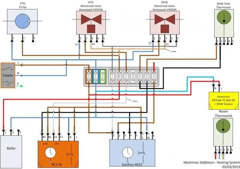
When it comes to controlling the flow of gas in a heating system, a gas valve plays a crucial role. And understanding how to wire a gas valve correctly is essential for the safe and efficient operation of any gas-powered device. In this article, we will delve into the details of a 3 wire gas valve wiring diagram, providing you with all the information you need to ensure a proper installation and performance.
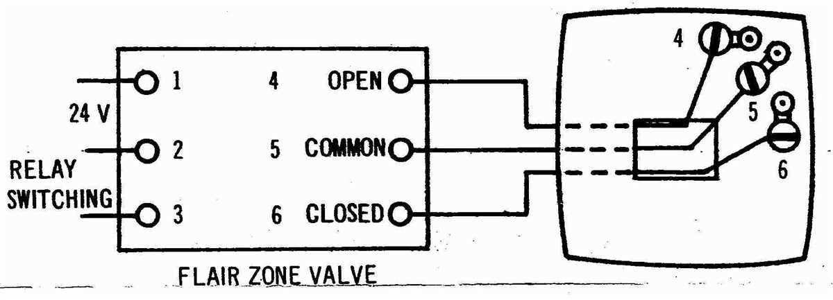
A 3 wire gas valve is commonly used in heating systems, such as furnaces and boilers. It is responsible for controlling the amount of gas that flows into the burner, ensuring a consistent and controlled flame. The wiring diagram for a 3 wire gas valve consists of three terminals: a common terminal, a power terminal, and a control terminal.
The common terminal is typically connected to the main gas supply. It serves as a grounding point for the valve and ensures that the electrical current flows properly. The power terminal is connected to a power source, providing the necessary voltage for the valve to open and close. Finally, the control terminal is connected to a control device, such as a thermostat or a pressure switch, which signals the valve when to open and close.
Understanding the Basics of 3 Wire Gas Valve Wiring
In the world of HVAC systems, gas valves play a crucial role in controlling the flow of gas to the burner. A 3 wire gas valve, as the name suggests, uses three wires for its electrical connections. Understanding the basics of 3 wire gas valve wiring is essential for proper installation and troubleshooting.
The three wires in a 3 wire gas valve setup typically include a power supply wire, a control wire, and a common wire. The power supply wire provides the necessary voltage to open and close the valve, while the control wire carries signals from the thermostat to the valve. The common wire completes the electrical circuit.
When it comes to wiring a 3 wire gas valve, it’s important to follow the manufacturer’s wiring diagram carefully. This diagram provides a visual representation of how the wires should be connected to the terminals on the valve. Each wire must be connected to the correct terminal to ensure proper operation of the gas valve.
The power supply wire is typically connected to the “H” or “Hot” terminal on the valve, while the control wire is connected to the “C” or “Control” terminal. The common wire is connected to the “C” or “Common” terminal, completing the circuit. It’s crucial to double-check the wiring connections and ensure that they are secure.
Proper wiring of a 3 wire gas valve is crucial for the safe and efficient operation of an HVAC system. Incorrect wiring can lead to malfunctions, furnace shutdowns, or even safety hazards. If you’re not confident in your wiring abilities, it’s always best to consult a professional HVAC technician who can ensure that the gas valve is wired correctly.
What is a 3 Wire Gas Valve Wiring Diagram?
A 3 wire gas valve wiring diagram is a graphical representation of the wiring connections for a gas valve in a heating system that uses three wires for control. Gas valves are essential components in furnaces, boilers, and other gas-powered heating systems, as they control the flow of gas to the burners.
The wiring diagram provides a visual guide for connecting the three wires of the gas valve to the corresponding terminals on the control board or thermostat. Each wire is assigned a specific function, such as supplying power, controlling the opening and closing of the valve, or sensing the flame. The diagram ensures that the correct connections are made, reducing the risk of wiring errors and system malfunctions.
The three wires commonly used in gas valve wiring are the 24-volt power wire (usually labeled as R or Rh), the valve control wire (usually labeled as W or W1), and the flame sensor wire (usually labeled as C or common). The power wire carries the electrical supply from the control board or thermostat to the gas valve. The valve control wire is used to open or close the gas valve based on the heating system’s demand for heat. The flame sensor wire detects the presence of a flame and provides feedback to the control board to ensure safe operation.
In some cases, additional wires may be present, depending on the specific system configuration. The wiring diagram helps identify the correct terminals for these additional wires, enabling proper integration into the overall heating system.
Overall, a 3 wire gas valve wiring diagram is an invaluable tool for technicians, installers, and DIY enthusiasts, as it ensures the correct and safe installation of gas valves in heating systems. Proper wiring is crucial for the efficient operation and longevity of the system, making the diagram an essential resource for anyone working with gas-fired heating equipment.
Components of a 3 Wire Gas Valve Wiring Diagram
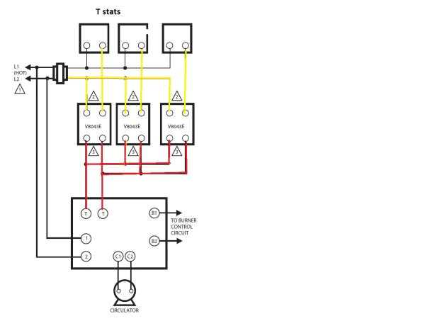
In a 3 wire gas valve wiring diagram, there are several key components that play important roles in the operation of the gas valve. These components work together to ensure the proper control and function of the gas valve in a heating system.
The main components of a 3 wire gas valve wiring diagram include:
- Gas Valve: The gas valve is the central component that controls the flow of gas into the heating system. It typically consists of an inlet port for gas supply, an outlet port for gas flow to the burners, and a valve mechanism that opens and closes to regulate the gas flow.
- Thermostat: The thermostat is a temperature-sensitive device that detects the current temperature of the space being heated. It sends a signal to the gas valve to open or close based on the desired temperature set by the user.
- Control Board: The control board acts as the central control unit for the heating system. It receives inputs from the thermostat and other sensors, and sends signals to various components, including the gas valve, to regulate the operation of the system.
- Transformer: The transformer converts the main electrical supply voltage to a lower voltage that is suitable for the control board and other components. It provides the necessary power for the operation of the gas valve and other electrical components in the system.
- Safety Devices: The gas valve wiring diagram may also include various safety devices, such as pressure switches and flame sensors, that are designed to detect abnormal conditions and shut off the gas supply if necessary. These devices help ensure the safety and reliability of the heating system.
In summary, a 3 wire gas valve wiring diagram includes components such as the gas valve, thermostat, control board, transformer, and safety devices. These components work together to regulate the flow of gas and ensure the safe and efficient operation of the heating system.
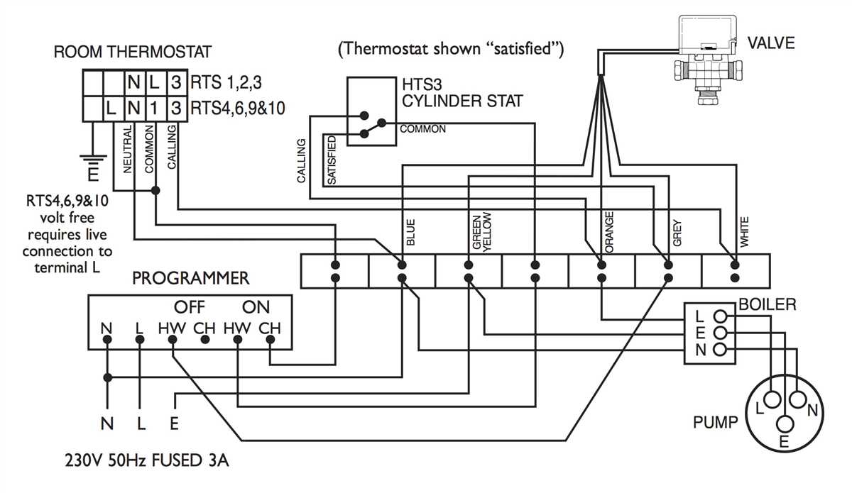
Wiring Instructions for a 3 Wire Gas Valve
When installing a gas valve with 3 wires, it is important to follow the proper wiring instructions to ensure proper functionality and safety. The 3 wire gas valve typically consists of a common wire, a power wire, and a control wire.
To begin the wiring process, it is essential to identify the common wire, power wire, and control wire. The common wire is usually labeled “C” and is used to provide a common ground connection. The power wire, labeled “P” or “H”, provides the main power supply to the valve. The control wire, labeled “T” or “TH”, is used to send control signals to the valve.
Once the wires have been identified, the next step is to connect them correctly. The common wire should be connected to the terminal marked “C” on the valve. The power wire should be connected to the terminal marked “P” or “H”, and the control wire should be connected to the terminal marked “T” or “TH”. It is important to ensure that the wires are securely connected and properly insulated to prevent any electrical hazards.
After the wiring is complete, it is essential to check the connections and test the functionality of the gas valve. This can be done by turning on the gas supply and activating the control system. If the gas valve opens and closes properly, and the control system operates as expected, then the wiring is correctly installed.
It is recommended to refer to the manufacturer’s instructions or consult a professional if there are any doubts or uncertainties during the wiring process. Following the proper wiring instructions for a 3 wire gas valve is crucial for the safe and efficient operation of the valve and the overall gas system.
Common Issues and Troubleshooting
When it comes to wiring a 3-wire gas valve, there are a few common issues that can arise. Understanding these issues and knowing how to troubleshoot them can help you avoid costly repairs and ensure proper operation of your gas valve.
1. Incorrect Wiring: One of the most common issues is incorrect wiring. It is important to carefully follow the wiring diagram provided with your gas valve to ensure that the wires are connected correctly. Double-checking your connections can help identify any wiring errors that may be causing issues.
2. Faulty Wiring Connections: Faulty wiring connections can also cause problems with the gas valve. Loose or corroded connections can disrupt the flow of electricity, leading to issues such as intermittent operation or a complete failure of the valve. Inspecting and tightening any loose connections can help resolve these issues.
3. Electrical Power Issues: Another potential issue is a lack of electrical power reaching the gas valve. This can be caused by a tripped circuit breaker, a blown fuse, or a problem with the electrical supply. Checking the power source and resetting any breakers or replacing fuses as necessary can solve this problem.
4. Faulty Gas Valve: In some cases, the gas valve itself may be faulty. This can occur due to age, wear and tear, or manufacturing defects. If all wiring connections and power supply are correct, and the valve still does not operate, it may be necessary to replace the gas valve.
By being aware of these common issues and knowing how to troubleshoot them, you can ensure the proper functioning of your 3-wire gas valve and avoid unnecessary repairs or replacements.
Safety Precautions for Installing a 3 Wire Gas Valve

When installing a 3 wire gas valve, it is important to take certain safety precautions to ensure the installation process is done correctly and safely. Here are some key points to keep in mind:
- Turn off the gas supply: Before attempting to install the gas valve, make sure to turn off the gas supply to the system. This will help prevent any accidental gas leaks or ignition during the installation process.
- Follow manufacturer instructions: It is crucial to carefully read and follow the manufacturer’s instructions provided with the 3 wire gas valve. Each gas valve may have specific installation requirements and guidelines that need to be followed for proper operation.
- Use proper tools and equipment: Make sure to use the appropriate tools and equipment for the installation. This may include wrenches, screwdrivers, and other necessary tools. Using the correct tools will help ensure a secure and reliable installation.
- Inspect the gas valve and wiring: Before installation, thoroughly inspect the gas valve and wiring for any damage or defects. If any issues are found, repair or replace the damaged components before proceeding with the installation.
- Securely connect the wiring: Take extra care when connecting the wiring to the gas valve. Make sure to securely tighten any connections and ensure proper insulation for electrical safety. Loose or faulty wiring can lead to dangerous situations, such as short circuits or electrical shocks.
- Test for gas leaks: After the installation is complete, it is essential to test for any gas leaks. Apply a mixture of soapy water to the gas valve connections and observe for any bubbles. If bubbles form, this indicates a gas leak, and immediate action should be taken to rectify the issue.
Overall, installing a 3 wire gas valve requires careful attention to safety measures. By following these precautions and being diligent throughout the installation process, you can ensure a safe and effective installation of a 3 wire gas valve.