For proper installation, identify the three essential conductors: power supply, ground, and trigger signal. The positive lead must connect directly to a stable voltage source within the recommended range, typically 12 to 24 volts DC.
The negative terminal should be linked securely to the chassis or common return path to ensure reliable operation and prevent electrical noise.
Signal input requires a dedicated control wire that activates the illumination pulse. This conductor often receives a switched positive voltage or a low-voltage trigger, depending on the manufacturer’s specifications.
Ensure all contacts are properly insulated and firmly attached to avoid intermittent faults. Use appropriately rated connectors and verify polarity before powering the system to protect sensitive components.
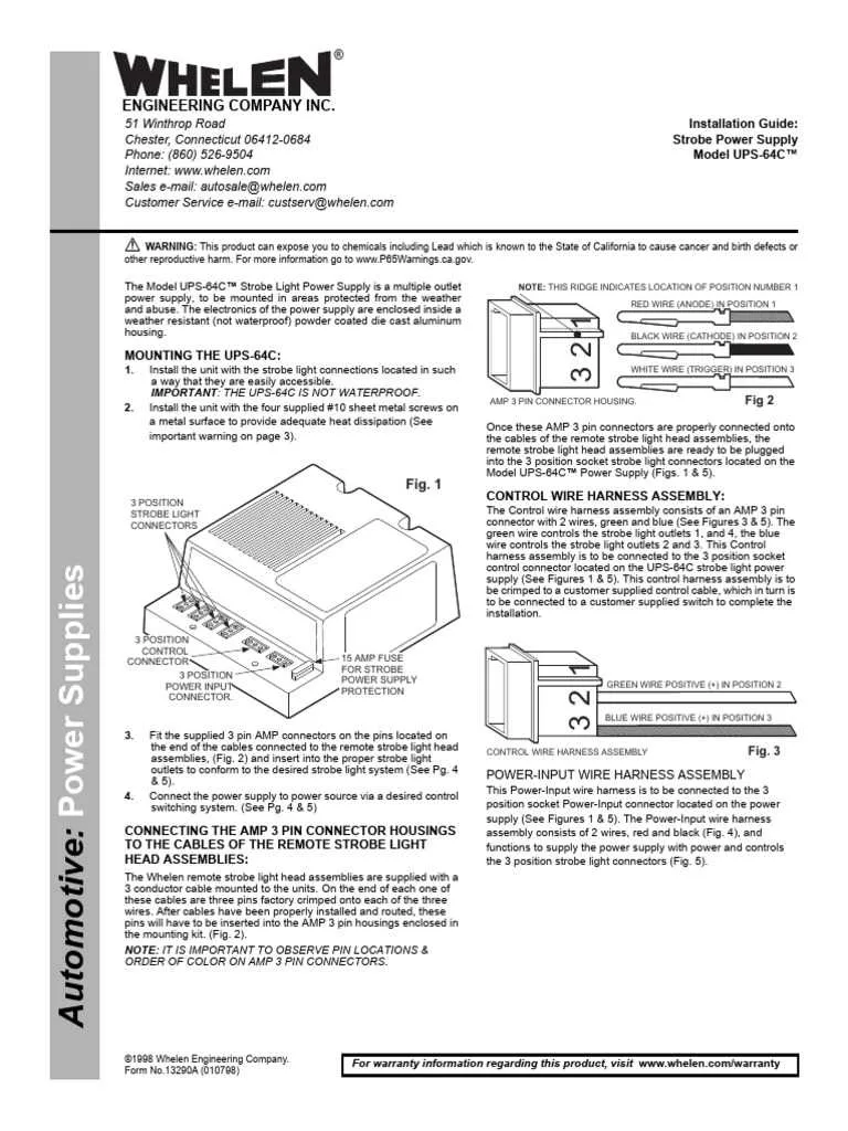
3 Wire Strobe Light Wiring Diagram

Connect the power lead to a 12V DC supply with a suitable fuse rated between 3A and 5A to protect the circuit. The ground cable must be securely attached to the vehicle chassis or common negative terminal to ensure proper operation.
The third conductor serves as the trigger input; it should be connected to the switch output or alarm system control signal. Use a relay if the trigger source cannot handle the current directly, ensuring isolation and preventing damage.
Verify all connections using a multimeter before powering the device to avoid shorts or reversed polarity, which could cause malfunction or permanent damage. Employ heat shrink tubing or insulated terminals to prevent accidental contact.
For optimal performance, keep all leads as short as possible and avoid routing near high-current lines to minimize electromagnetic interference. Confirm the pulse rate matches the manufacturer’s specifications to achieve the correct flashing effect.
Identifying Each Cable Function and Connection
To ensure proper installation, assign each conductor according to its specific role and terminal point:
- Positive Lead (Power): Typically red, this conductor delivers the main voltage source, usually 12V or 24V DC, depending on the system requirements. Connect this to the vehicle’s or power supply’s positive output.
- Ground Line: Usually black, this line must be attached to a solid chassis ground or negative terminal to complete the electrical circuit and prevent malfunction.
- Trigger Signal: Often white or blue, this conductor receives the activation pulse from the control switch or relay. It controls the flash timing by supplying intermittent current.
Confirm polarity and color codes with a multimeter before making connections to avoid damage. Secure all terminals tightly and insulate exposed contacts to prevent shorts.
Step-by-Step Wiring Process for Common Vehicle Installations
Start by connecting the black lead to a clean chassis ground point, ensuring firm metal-to-metal contact without paint or rust. Secure with a ring terminal and self-tapping screw if needed.
Route the red conductor to the fuse panel or battery positive terminal. Integrate an inline fuse holder rated for 5A–10A based on the product’s load specification. Crimp connections with heat-shrink terminals to prevent moisture intrusion.
Attach the third (usually yellow or white) signal input to the controller or auxiliary switch. Use a relay if interfacing with factory electronics to avoid overload or feedback. Confirm compatibility with 12V triggers and test using a multimeter before final connection.
Bundle all paths with split loom tubing and secure using zip ties every 12 inches. Avoid routing near hot surfaces or moving components like fan assemblies or suspension parts.
Before reassembling trim panels, verify operation by activating the control input and observing function across all modes. Confirm proper shutdown upon power removal to prevent battery drain.
Troubleshooting Signal and Power Issues in 3 Wire Systems
Start by verifying voltage levels between the ground return and the control input using a multimeter. A stable reading around 12V or 24V, depending on the system design, confirms correct power delivery. Fluctuations indicate grounding faults or unstable supply sources.
Check continuity on the return path using the resistance mode. Resistance above 1 ohm may signify oxidation or a partially broken trace. Clean all contact points and reseat connectors securely.
Inspect the control trigger by applying a known signal pulse. If activation fails despite proper voltage, the controller may be shorted or the logic signal mismatched. Use an oscilloscope to confirm pulse shape and duration.
Isolate the output channel by disconnecting the downstream device. If the source resumes correct operation, the endpoint unit may be drawing excessive current or has internal faults. Measure current draw during idle and active states; values exceeding the design limit suggest a failing load.
Examine insulation on all leads for signs of thermal damage or wear. Shorts to chassis or other channels can disrupt both signal integrity and power stability. Use insulation testers for high-accuracy diagnostics.
Confirm polarity alignment across connectors, especially in field installations. Reversed connections can cause transient faults or permanent controller failure. Label all points clearly to prevent incorrect mating during maintenance.