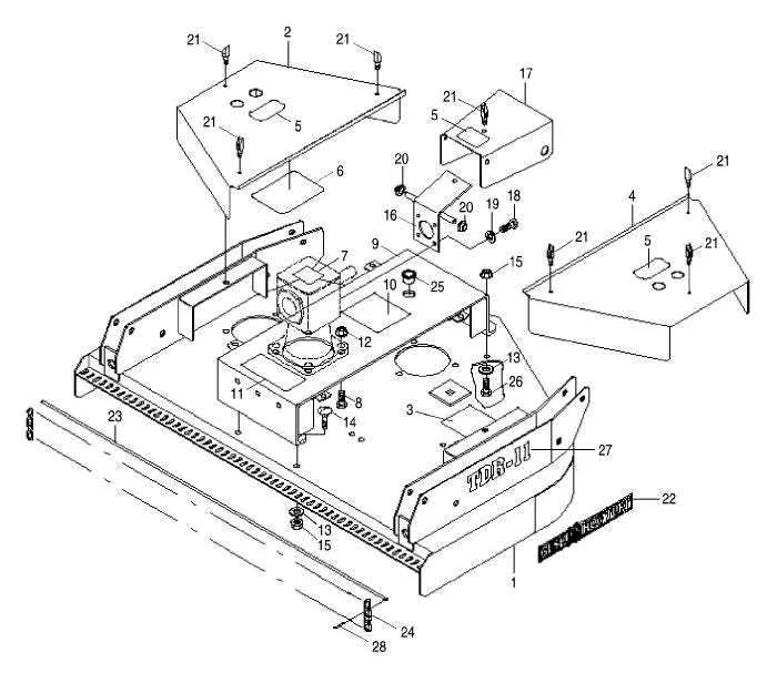
Begin by inspecting the gearbox housing located at the center-top area of the implement. Look for a splined shaft emerging vertically–this connects to the input drive from the tractor’s PTO. Surrounding the gearbox, you’ll typically find four mounting bolts and a vented cap for pressure regulation. If fluid leakage is observed, replacing the seal kit is essential.
Move to the rotating assembly underneath, where the primary blade carrier–commonly referred to as the stump jumper–is mounted. This disc-like component holds two swinging blades and is fastened to the output shaft using a castle nut and cotter pin. Ensure all elements are free of cracks, especially around the mounting holes.
Check the tail wheel assembly at the rear frame. The yoke supports a solid rubber tire, fixed via a spindle and greased axle. Confirm that the fork pivots smoothly and that the mounting bracket hasn’t developed fatigue cracks. Use a digital caliper to measure any wear in the spindle bore if the wheel appears misaligned.
Examine the side skids and support brackets along both edges of the main deck. These skids act as guides and height stabilizers. Verify that the wear is even across their length and that attachment bolts are secure. If excessive bending or rust-through occurs, consider welding reinforcement plates before continuing operation.
Component Layout for Rotary Cutter Assemblies
Start by identifying the gearbox location–typically mounted centrally above the blade hub. Ensure the output shaft is aligned with the blade carrier; misalignment can cause premature wear. The driveline should connect securely from the PTO shaft to the gearbox input, with proper shielding intact for operator safety.
Blades are bolted to the carrier plate using hardened fasteners. Inspect for uniform torque and signs of fatigue or cracking. Underneath, the stump jumper disc provides deflection and should spin freely without contact against the housing.
Skid plates attach along the lower sides of the frame, protecting structural edges during ground contact. These are usually held in place with carriage bolts and lock nuts. Check for bends or rust that could compromise field performance.
The rear tailwheel assembly includes a yoke, fork, and caster hub. Ensure bearings rotate smoothly and the vertical height adjustment pin is locked to maintain mowing level. Grease fittings should be present on the spindle and axle pivots.
Shielding components, such as chain guards or rubber flaps, are fixed along the front and rear openings. These barriers must be intact to reduce debris ejection. Replace damaged segments using the appropriate mounting brackets and cotter pins.
Identifying Blade Assembly Components in Bush Hog Schematics
Start by locating the central mounting hub, typically positioned at the underside of the rotary deck. This hub connects directly to the gearbox output shaft and serves as the anchor for all cutting attachments.
- Blade carrier: A heavy circular disc or bar that distributes torque from the shaft to the knives. Check for a keyed or splined connection to ensure correct alignment.
- Cutting edges: Each unit uses two pivoting knives bolted to the carrier. Confirm orientation–sharp edge faces the direction of rotation, and the curve follows the airflow pattern.
- Fasteners: Use grade 8 bolts with locking nuts or castle nuts and cotter pins. Inspect for wear grooves or elongation in bolt holes.
- Retainer cups or washers: Found between the carrier and knife to allow controlled swing and reduce metal-on-metal friction. Look for signs of deformation or cracks.
- Spacer collars: Positioned around bolts to maintain precise swing distance. Replace if crushed or uneven.
Reference the manufacturer’s schematic by tracing from the driveshaft flange down to the blade mounting plane. Use torque specs and thread-locking compounds during reassembly to prevent component loosening during operation.
Understanding Gearbox Layouts and Connection Points
Always inspect the input shaft orientation before mounting; horizontal or vertical alignment dictates compatible driveline angles. Confirm spline count and diameter–common options include 1-3/8″ 6-spline and 1-3/4″ 20-spline types–to ensure proper coupling with PTO assemblies.
Identify mounting flange configurations: four-bolt square and six-bolt round patterns are typical. Verify hole spacing using calipers for accurate substitution when replacing worn units. Secure torque specifications are essential; use a calibrated wrench to apply 120–150 ft-lbs on main fasteners unless otherwise noted in the technical sheet.
Grease zerks located on the bearing housings must be accessible post-installation. Improper alignment can obstruct maintenance intervals and lead to premature wear. For top-mounted assemblies, confirm that vent plugs are free from debris to avoid pressure buildup during operation.
Where applicable, match the gear ratio–frequently 1:1 or 1:1.46–to rotational requirements of connected rotary mechanisms. Exceeding rated horsepower thresholds, often stamped directly on the housing, can compromise internal bevel gears and seals.
Locating Safety Shield and Guard Mounting Positions
Mount all protective covers precisely at the factory-specified attachment points on the rotary cutter frame. Key mounting brackets are typically found near the PTO shaft housing and along the side arms where guard flanges are integrated.
Ensure the safety shields align flush with the driveline components, maintaining a clearance of no more than 1/4 inch to prevent vibration but avoid contact. Mounting holes are often pre-drilled on the main chassis near the gearbox and rear axle supports.
For rear and side deflectors, fasten using the heavy-duty tabs welded adjacent to the blade housing skirt. Use lock washers to secure bolts, preventing loosening during operation.
Check the condition of mounting brackets before installation; replace any bent or cracked elements to maintain structural integrity of the protective system. Position guards to fully cover rotating assemblies without restricting blade movement.
When reassembling shields after maintenance, follow torque specifications closely–typically between 18 to 25 Nm–to balance firmness and flexibility. Confirm that all mounting hardware is compatible with the cutter model to ensure proper fit and safety compliance.