For optimal performance, ensure your system is configured with the right connections. A 36V configuration requires precise planning to maximize efficiency and power output. The key steps include ensuring correct battery placement, selecting appropriate connectors, and wiring each component with precision.
First, connect the batteries in series to achieve the desired voltage. Use a reliable fuse between the battery pack and the controller to prevent any electrical overload. Always check the voltage output before making connections to avoid potential damage.
Next, confirm the polarity of the connections. Reversing the positive and negative leads can result in malfunction. Use heavy-duty cables capable of handling the increased current flow and prevent overheating. Don’t forget to secure all connections tightly to avoid wear and tear during operation.
Proper grounding is essential to avoid short circuits. Ensure all components are grounded properly before the system is powered on. Once everything is connected, test the system incrementally to check for any anomalies or failures in the system’s responsiveness.
Lastly, remember that regular maintenance and checking of all components, such as controllers and batteries, will keep the system running smoothly for years.
Wiring Guide for 36V Electric Propulsion System
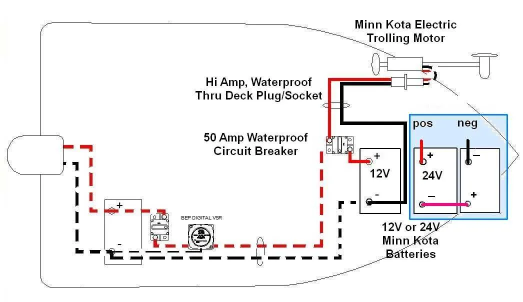
For proper setup, ensure that the battery pack is composed of three 12V batteries connected in series to provide the necessary voltage. The positive terminal of the first battery should be connected to the power input, while the negative terminal of the third battery is grounded to the frame of the vessel.
Use a 10 AWG cable for the main connection between the batteries and the electric drive. This ensures enough current flow without significant voltage drop. Secure each connection with heavy-duty ring terminals and ensure that the connections are tight to avoid power loss or heating.
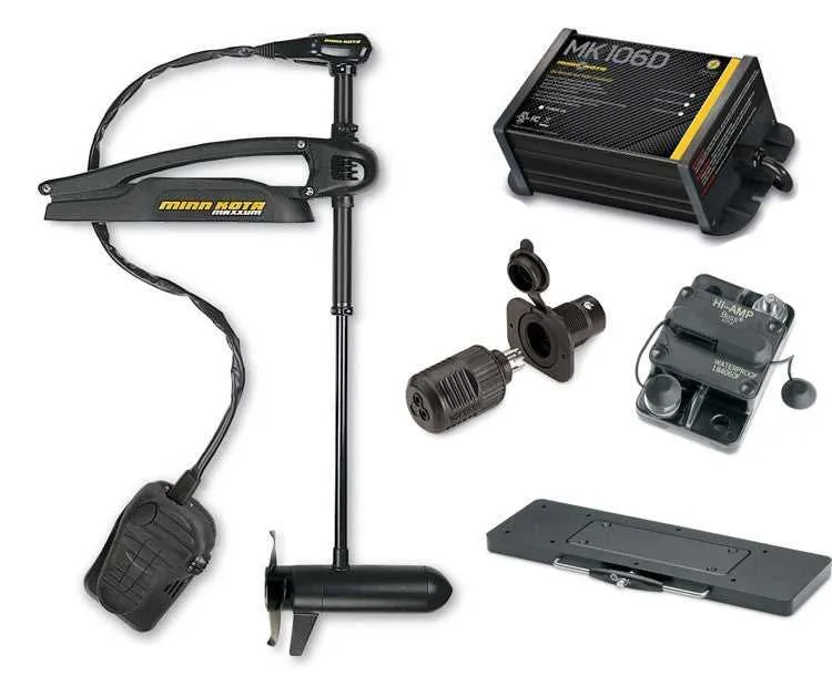
The control unit, typically located near the helm, should be wired to the power system using a sealed connector to prevent moisture ingress. A fuse or circuit breaker rated at 40-50 amps should be placed near the battery pack for overload protection.
For the throttle or speed controller, connect the wires following the manufacturer’s manual, ensuring the positive and negative leads are correctly matched. Ground the system to the vessel’s metal frame to prevent electrical interference and ensure stability of the entire system.
When installing, make sure that the wire lengths are kept as short as possible to reduce resistance and optimize performance. Test the system before operation to confirm that the power distribution is correct and that no connections are overheating.
Choosing the Right Wire Gauge for a 36V Electric Propulsion System Setup

For optimal performance, choose a wire gauge that matches the current draw and distance between the power source and the propulsion system. For setups requiring 50-60 amps of current, 6 AWG wire is a standard choice, offering a good balance between conductivity and flexibility. For longer distances, increase the gauge size to 4 AWG or even 2 AWG to reduce voltage drop and ensure reliable operation.
Use higher gauge wires for shorter runs to maintain efficiency and minimize bulk. Conversely, when wires run longer distances or higher amperage is involved, consider lower gauge wires to handle the load without overheating. Always consider the maximum ampacity of the wire and match it with your system’s requirements to avoid safety hazards.
Additionally, check for marine-grade wire, especially for setups exposed to water, to ensure corrosion resistance and durability over time. Make sure all connections are properly sealed to prevent issues with moisture ingress.
Step-by-Step Process for Connecting a 36V Power System to a Battery Bank

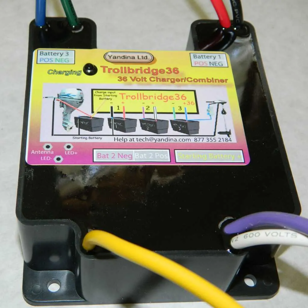
Start by placing your three 12V batteries in series. Connect the positive terminal of the first battery to the negative terminal of the second, and then the positive terminal of the second to the negative terminal of the third. This setup creates a unified power source of 36V.
Next, secure the cables from the system’s output to the terminals of your power source. Use a heavy-duty cable to avoid voltage drop. Attach the positive cable to the system’s positive terminal and the negative cable to the negative terminal of the power unit.
Afterward, connect the negative lead from the power unit to the negative terminal on the battery pack. Ensure a tight connection to prevent any loss of power or short circuits. Follow this by linking the positive lead to the positive terminal of the battery pack in the same manner.
Install a fuse or circuit breaker between the positive terminal of the battery bank and the positive terminal of the unit. This will protect the system from power surges and prevent potential damage from overcurrent situations.
Finally, verify that all connections are secure, and check for any possible short circuits before activating the system. Properly securing the wires in place will ensure the longevity and efficiency of the setup.
Understanding Circuit Protection and Fusing for 36V Electric Propulsion Systems
For optimal safety and longevity of your 36V propulsion system, it is critical to implement the right circuit protection and fusing. Without adequate protection, your setup can suffer from electrical damage or fires due to excessive current flow.
Follow these recommendations for proper protection:
- Use a fuse rated for the maximum current your system will draw. For most setups, a fuse with a 60A or 70A rating should suffice, depending on your system’s specifications.
- Ensure fuses are placed as close as possible to the battery to minimize the risk of damage from short circuits.
- Consider an automatic reset circuit breaker, which can prevent damage while offering the ability to reset after an overload, especially in high-demand scenarios.
Choose the appropriate fuse or circuit breaker based on these factors:
- Maximum amperage rating of the system. Typically, 60-70A fuses handle most setups effectively.
- Wire gauge: Ensure that the fuse matches the wire size to avoid wire overheating or melting.
- Environment: If the system will be exposed to moisture or rough conditions, opt for waterproof and rugged fuses or circuit breakers.
Incorrect fusing can lead to blown fuses or system failure, so always check manufacturer recommendations for fuse ratings specific to your system’s design.