Understanding the electrical layout of your vehicle can be crucial for troubleshooting and repairs. If you own a 1997 model, familiarizing yourself with the placement of the various relays and circuit connections will save you time and effort. The first step is identifying the location of key components such as the main power distribution panel and auxiliary fuse clusters.
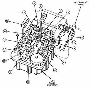
For the main panel, it’s typically located near the driver’s side, beneath the dashboard or within the engine compartment, depending on the vehicle’s design. This area houses multiple components responsible for directing power to various systems, such as lighting, ignition, and auxiliary functions. Knowing exactly where each of these systems draws power is essential for quick diagnosis.
Each fuse or relay in the assembly corresponds to specific electrical functions, so having a precise layout is vital. For example, a blown relay or fuse might affect everything from engine performance to the dashboard lights. With a clear understanding of the structure, you’ll know exactly which one to check or replace when a malfunction occurs.
Additionally, some models might have an auxiliary panel located in the passenger side footwell or under the seat. Be sure to consult the vehicle’s manual for specific locations if you’re unsure. Accurate knowledge of where these components reside will save you unnecessary disassembly and frustration.
97 Pickup Electrical Component Layout
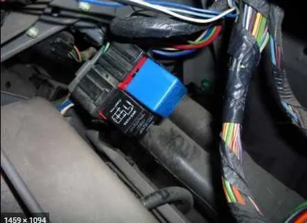
For troubleshooting or maintenance of the electrical system in a 1997 model, refer to the layout of the vehicle’s primary electrical connections. The main junctions are found both under the hood and within the cabin. Understanding the positioning of each circuit can save you time when addressing issues such as blown relays or malfunctioning components.
Under the engine compartment, the central power distribution area is located near the driver’s side, typically secured by a plastic cover. Key components within this area include high-current circuits for the alternator, headlights, and cooling system. For interior systems, the auxiliary power hub is situated below the dashboard, near the driver’s knee. This secondary junction serves circuits for interior lights, the air conditioning system, and audio components.
Each section is labeled clearly with either a printed label or molded numbers that correspond to specific connections. It’s essential to reference these markings when diagnosing or replacing individual electrical parts. Always use a multimeter to verify that the components are receiving correct voltage before assuming any parts are defective.
If you need a guide for the exact layout of each section, consult a service manual for detailed maps that include all wire routing and pinout configurations. These manuals will help you navigate through the various connections efficiently, ensuring that no critical systems are overlooked.
Locating the Electrical Panel in a 1997 Pickup

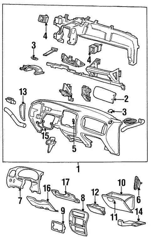
The primary control center for electrical components is positioned on the driver’s side, beneath the dashboard. To access it, remove the cover panel just below the steering wheel. You may need to use a flathead screwdriver to gently pry the cover off.
Additionally, there is another unit located in the engine compartment, near the battery. This is more accessible by opening the hood and locating the plastic panel on the driver’s side of the engine bay. A simple latch mechanism will allow you to remove the cover and gain access to the internal components.
Both locations are essential for troubleshooting electrical issues and should be regularly checked for damage or corrosion to ensure optimal performance.
Understanding Electrical Layout for Troubleshooting

To efficiently resolve electrical issues, start by familiarizing yourself with the vehicle’s main power distribution system. Knowing the layout of the components and their corresponding wiring helps in pinpointing the root cause of problems quickly.
Identify the key areas within the electrical setup where most issues occur: relays, circuits, and terminals. These components are critical in the distribution of power to various systems like lights, engine control, and the ignition system.
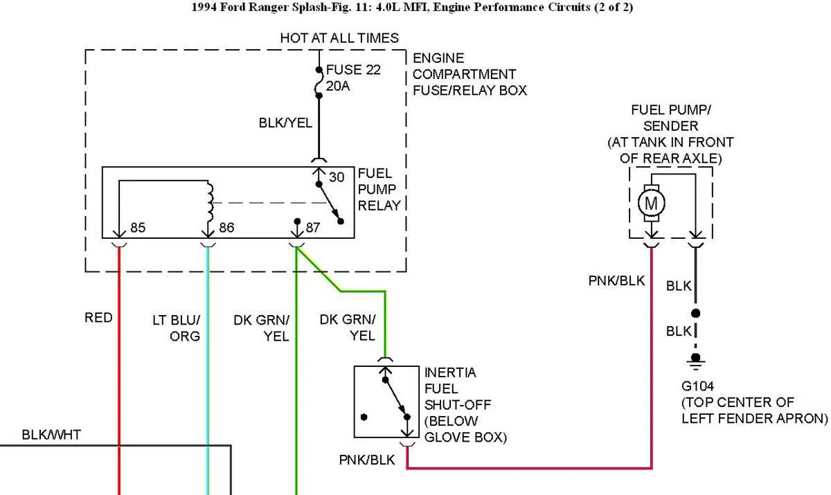
- Relays: These devices control high-power circuits with a low-current signal. Check for any burnt or malfunctioning relays, which are often located near the power distribution panel.
- Terminals: Loose or corroded terminals can cause intermittent power loss. Inspect all connections, especially the ground connections, as they play a significant role in maintaining a stable power flow.
- Power Supply: Ensure that the main power supply to the system is intact. A blown fuse or damaged wire can disrupt the flow, leading to failure in several systems.
When inspecting the layout, follow a step-by-step process:
- Locate the primary distribution area, often under the dashboard or in the engine bay.
- Consult the labeling for each circuit to understand its function, such as lights, HVAC, or ECU.
- Check for visible signs of damage such as burnt spots, frayed wires, or disconnected links.
- Test individual connections and components with a multimeter to verify continuity and voltage.
- Swap or replace damaged parts based on the findings.
Pay close attention to the color coding and numbering system used in the layout. Each circuit is usually assigned a specific color, which can help trace faults with precision. If multiple systems are malfunctioning simultaneously, it could indicate a central issue such as a malfunctioning relay or a blown primary fuse.
Thoroughly mapping out this area before proceeding with any repairs will save time and reduce unnecessary trial-and-error.
How to Replace Fuses in the 97 Ford Ranger Fuse Box

First, identify the location of the main electrical panel under the dashboard, near the driver’s side. Open the cover to access the wiring components. Each circuit within the panel is labeled to indicate its corresponding function–check the diagram for reference. Find the blown component by inspecting for a broken filament or discoloration inside. Use needle-nose pliers to carefully remove the faulty part.
Next, select a replacement of the same amperage rating to prevent damage to the wiring. Insert the new component into the same slot, ensuring it’s seated properly. Test the repaired circuit by switching on the ignition and confirming functionality of the affected system, such as lights or power windows. If the replacement does not resolve the issue, further diagnostics may be needed to check for underlying electrical faults.