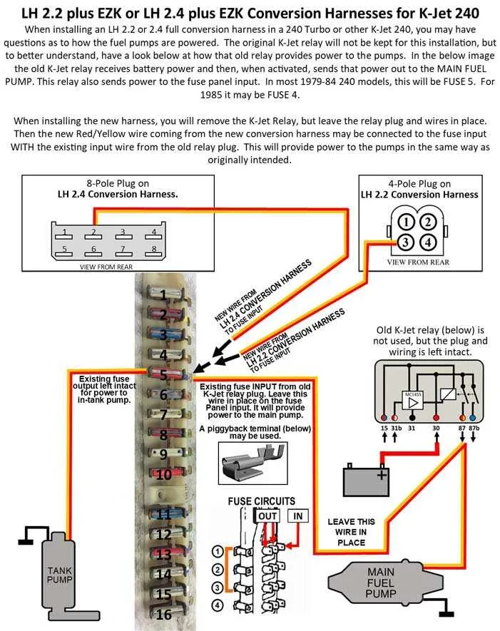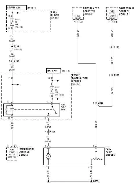
For proper installation, focus on ensuring the correct placement of the positive and negative terminals. These must be linked to their respective power sources and ground, with attention paid to voltage requirements. In addition, the signal and activation leads should be securely connected to the controlling unit for accurate operation.
The positive terminal typically receives 12V direct current, while the negative ensures a proper return path to the battery ground. Both the signal and activation terminals serve to regulate the functionality, often interacting with an ECU or similar module for precise timing and response.
For a reliable system, make sure each terminal is free from corrosion, and the connection points are tightly secured to prevent intermittent power loss. Regular checks of these terminals will prevent malfunctions and extend the lifespan of your unit.
4 Wire Fuel System Electrical Setup
To properly connect a 4-pin system, start by identifying the key components: the power source, ground, activation relay, and signal input. The power line connects to a 12V positive supply, while the ground pin ensures proper return to the battery’s negative terminal. The relay engages when the activation signal is received, completing the circuit.
The fourth connection usually serves as an auxiliary feature, often linked to a sensor or control unit that monitors operational conditions. Ensure that all connections are solid and insulated to avoid accidental shorts, and use a fuse to protect the system from overcurrent issues.
When installing, verify that the ground is securely attached to a clean metal surface to prevent poor connection or intermittent issues. For the signal input, follow the vehicle’s service manual to ensure correct pairing with the control unit. This will help avoid malfunction or incorrect activation.
Test the system with a multimeter to ensure proper voltage flow and continuity through each connection. After installation, check the system’s performance by cycling the ignition and observing the component’s response to activation.
Understanding the Function of Each Wire in a 4 Wire Fuel Pump
Each of the four connections plays a specific role in the proper operation of the system. Below is a breakdown of the essential components:
- Power Supply: This connection provides the necessary voltage from the vehicle’s battery to initiate the motor’s operation.
- Ground Connection: This wire connects to the vehicle’s chassis or ground, completing the circuit and allowing the motor to function.
- Signal for Activation: This input triggers the motor to begin its function when the engine requires it, often controlled by the vehicle’s ECU or relay.
- Sensor Output: This wire sends feedback to the system, indicating the operational state of the component, often used for diagnostics or feedback control.
Ensuring each is connected correctly is critical for efficient and safe operation.
Step-by-Step Installation Instructions for a 4 Wire Fuel System

1. Identify the Connections
Ensure that all components are clearly marked. The four conductors typically consist of a ground, a constant power, an ignition switch signal, and a relay trigger. Verify each one before connecting to avoid any confusion during installation.
2. Grounding the System
Attach the grounding lead to a clean, rust-free part of the chassis. Ensure this connection is tight to avoid interruptions in the system’s operation. A poor ground can lead to voltage drops, reducing efficiency.
3. Constant Power Source
Connect the power conductor to a consistent 12V source, usually the battery or a direct fuse box connection. Ensure the power supply is stable and able to handle the required load for the system’s operation.
4. Connecting the Ignition Signal
This conductor should link to the ignition switch to activate the system when the vehicle is started. Use a circuit tester to verify the ignition switch’s functionality before making the connection.
5. Relay Trigger
The trigger lead should be wired to a relay that can be activated by the ignition signal. Use a high-quality relay designed to handle the current load of the system to avoid overheating or failure.
6. Double-Check All Connections
Before powering up, inspect all connections to ensure they are secure and correctly positioned. Use electrical tape or connectors to prevent any short circuits. Incorrect connections can cause malfunction or damage to the entire setup.
7. Testing the System
Once everything is hooked up, turn the ignition to the “ON” position without starting the engine. Verify that the system activates correctly. If it doesn’t, troubleshoot each connection and ensure the relay and ignition signal are functioning as expected.
8. Final Adjustments
After testing, make any final adjustments to the setup. Secure all wires in place using cable ties and ensure nothing is exposed to high heat areas. This ensures longevity and prevents any wear or damage to the connections over time.
Troubleshooting Common Issues with 4 Wire Fuel Pump Wiring
Ensure the power source is delivering proper voltage. A drop in voltage can result in insufficient operation. If the voltage checks out, examine the connections for corrosion or looseness. Even small disruptions can cause failure to engage. Tighten any loose connections and clean terminals with an appropriate solution to improve conductivity.
Next, verify the ground path. A weak or interrupted ground connection is a common culprit for malfunction. If the grounding is compromised, the device may not activate correctly. Check for any signs of wear or breaks in the grounding circuit and fix as needed.
If the motor is not operating despite power and ground checks, test the relay. The relay is responsible for activating the motor, and if it’s faulty, the system won’t engage. Test continuity across the relay and replace if necessary.
Inspect the signal line for correct function. A failure to send the appropriate signal can prevent the motor from running. Use a multimeter to check for any abnormal readings and replace the control unit if necessary.
Finally, ensure that the protective fuse has not blown. A damaged fuse can interrupt the entire system’s function. Replace any faulty fuses with ones of the correct rating to restore the circuit’s integrity.