
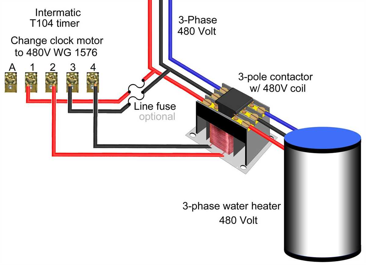
When it comes to wiring a 480 volt 3 phase motor, it’s important to understand the different components and connections involved. Whether you’re an experienced electrician or just getting started, having a detailed wiring diagram can be immensely helpful in ensuring a successful installation.
A 480 volt motor requires a robust electrical system to handle the higher voltage and power. In a 3 phase system, power is distributed using three hot wires, each carrying 120 volts. These hot wires are connected to the motor through the motor starter, which includes a contactor and overload protection devices.
The wiring diagram for a 480 volt 3 phase motor will show the connections between the motor’s terminals and the different components of the electrical system. It will typically include labels and color-coded wires to make it easier to understand and follow. Additionally, the diagram may also indicate the sizes of the wires and the specific voltages and currents associated with each connection.
Proper wiring is crucial for the safe and efficient operation of a 480 volt 3 phase motor. It’s important to carefully follow the wiring diagram and ensure that all connections are made correctly. This will help prevent electrical hazards and ensure that the motor functions properly.
Understanding 480 Volt 3 Phase Motor Wiring Diagram
In the world of industrial machinery and equipment, the 480 volt 3 phase motor is a common component. To properly install and wire this motor, it is essential to understand the wiring diagram. The diagram provides important information about the motor’s connections and shows how the various wires should be connected to ensure proper operation.
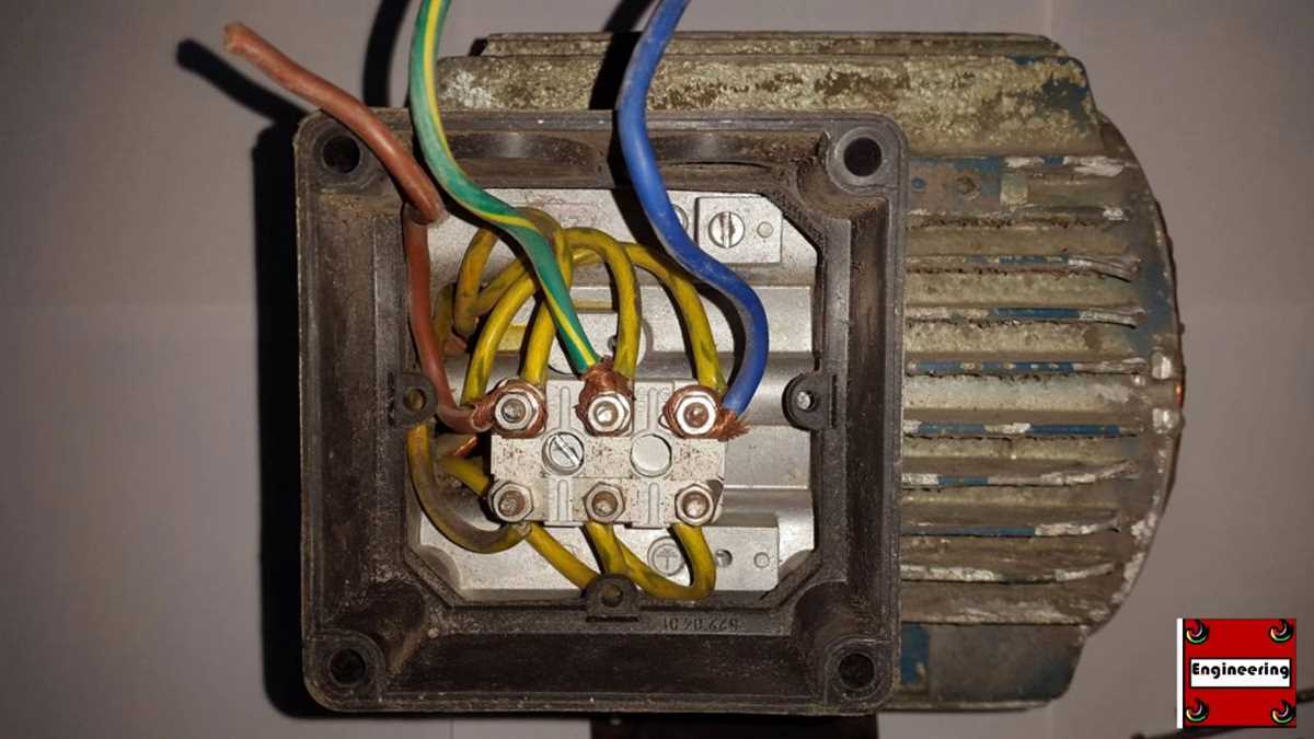
When working with a 480 volt 3 phase motor, it is important to remember that there are three hot wires and one ground wire. The hot wires, also known as phase wires, carry the electrical current and are labeled A, B, and C. These wires are connected to corresponding terminals on the motor using wire nuts or terminal blocks.
The wiring diagram also shows the location of the neutral terminal, which is typically labeled “N” or “Nuet” on the motor. The neutral wire should be connected to this terminal to complete the circuit. Additionally, the diagram may indicate the location of other terminals, such as those for a start or run capacitor, if applicable.
It is important to follow the wiring diagram precisely to ensure proper installation. Making incorrect connections can lead to motor failure or even hazardous conditions. If you are unsure about any aspect of the wiring process, it is recommended to consult a qualified electrician or refer to the manufacturer’s instructions.
To summarize, understanding the wiring diagram for a 480 volt 3 phase motor is crucial for proper installation and operation. By carefully following the diagram and making the correct connections, you can ensure the motor functions safely and efficiently in your industrial application.
What is a 480 Volt 3 Phase Motor?
A 480 Volt 3 Phase Motor is a type of electric motor that is designed to operate with a three-phase power supply at a voltage rating of 480 volts. This type of motor is commonly used in industrial and commercial applications where high power and efficiency are required.
Three-phase power: In a three-phase power system, the power supply consists of three separate voltage waveforms that are phased 120 degrees apart. This allows for a more efficient power transfer and reduces the need for large and expensive power transmission equipment. Three-phase power is commonly used in industrial settings because it provides a more stable and reliable power supply.
480 volts: The voltage rating of 480 volts is a common standard for industrial and commercial power systems. This higher voltage allows for the efficient operation of electrical equipment and motors, which require higher power outputs. The 480-volt rating is often chosen for its ability to provide sufficient power while still maintaining a safe and manageable level of electrical current.
Motor design: A 480 Volt 3 Phase Motor is specifically designed to operate with a three-phase power supply at a voltage rating of 480 volts. These motors typically feature a robust construction and are designed to handle the high power and torque requirements of industrial applications. They may include features such as multiple windings and cooling systems to ensure reliable and efficient operation.
Wiring diagram: To properly connect and control a 480 Volt 3 Phase Motor, a wiring diagram is used. This diagram illustrates the electrical connections between the motor and the power supply, as well as any additional control components. Following the correct wiring diagram is essential to ensure safe and reliable operation of the motor.
In summary, a 480 Volt 3 Phase Motor is a powerful and efficient electric motor designed to operate with a three-phase power supply at a voltage rating of 480 volts. Its robust design and high power output make it ideal for industrial and commercial applications.
Benefits of Using a 480 Volt 3 Phase Motor
A 480 volt 3 phase motor offers several advantages over other types of motors. Here are some of the key benefits:
- Higher Power Output: A 480 volt 3 phase motor is capable of delivering a higher power output compared to single phase motors. This is because it uses three separate phases, allowing for a more efficient distribution of power.
- Improved Efficiency: Three phase motors are generally more efficient than single phase motors. The use of multiple phases in a 480 volt 3 phase motor reduces the amount of energy lost during transmission, resulting in improved overall efficiency and lower operating costs.
- Smooth Operation: Three phase motors provide smooth and consistent power delivery, which is ideal for applications that require constant torque and speed control. The three-phase power supply ensures that the motor operates smoothly without excessive vibration or fluctuations.
- Reduced Electrical Noise: Compared to single phase motors, 480 volt 3 phase motors produce less electrical noise and have lower harmonic distortion. This makes them suitable for sensitive electronic equipment and applications that require a clean power supply.
- Flexibility in Industrial Applications: Many industrial equipment and machinery are designed to operate with 480 volt 3 phase motors. By using this type of motor, businesses can easily integrate their equipment into existing systems and infrastructure without the need for costly modifications.
In summary, using a 480 volt 3 phase motor offers higher power output, improved efficiency, smooth operation, reduced electrical noise, and increased flexibility in industrial applications. These benefits make it a popular choice for various industrial and commercial applications that require reliable and efficient motor performance.
Basic Wiring Principles for a 480 Volt 3 Phase Motor
When it comes to wiring a 480 volt 3 phase motor, there are a few basic principles to keep in mind. Understanding these principles can help ensure a safe and efficient electrical connection for your motor.
First and foremost, it is important to understand the power supply requirements for a 480 volt 3 phase motor. This type of motor requires a three-phase power source with a voltage of 480 volts. It is crucial to verify that the power supply meets these specifications before attempting any wiring.
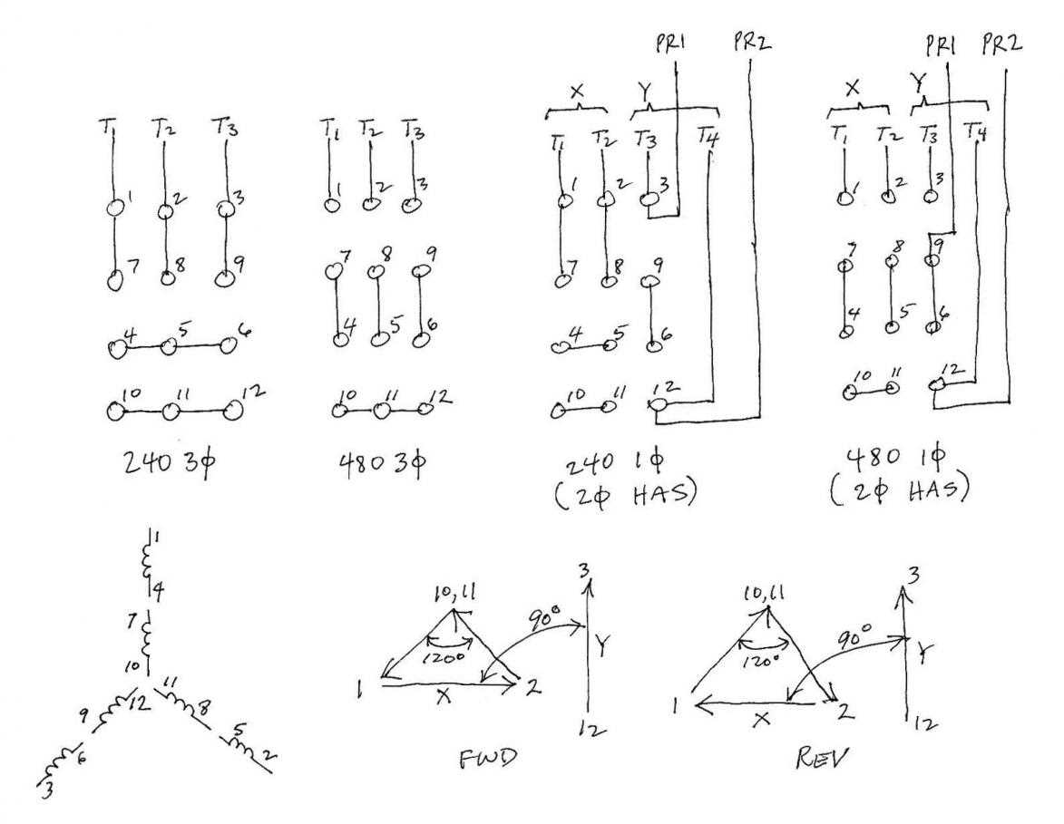
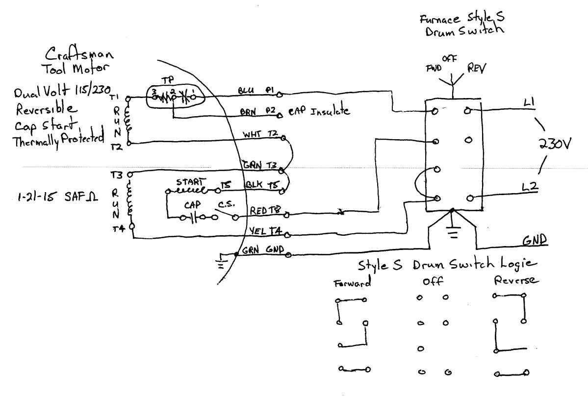
Once the power supply has been confirmed, the next step is to identify the motor’s terminals. A 480 volt 3 phase motor typically has nine terminals labeled T1, T2, T3, T4, T5, T6, T7, T8, and T9. These terminals are used to connect the motor to its power supply and control circuits.
In order to properly wire the motor, it is important to understand the wire color codes typically used for 480 volt 3 phase motors. The color coding for these wires is typically as follows: T1 – black, T2 – red, T3 – blue, T4 – white, T5 – orange, T6 – yellow, T7 – purple, T8 – brown, T9 – gray.
When connecting the motor to the power supply, it is important to follow the manufacturer’s wiring diagram. This diagram will provide specific instructions on how to connect each terminal to the correct power source or control circuit. It is crucial to double-check these connections and ensure they are secure and properly insulated.
In conclusion, wiring a 480 volt 3 phase motor requires understanding the power supply requirements, identifying the motor’s terminals, and following the manufacturer’s wiring diagram. By following these basic principles, you can ensure a safe and effective electrical connection for your motor.
Common Wiring Configurations for a 480 Volt 3 Phase Motor
When it comes to wiring a 480 volt 3 phase motor, there are several common configurations that are used for different applications. These configurations determine how the motor is connected to the power supply and can have an impact on the motor’s operation and performance.
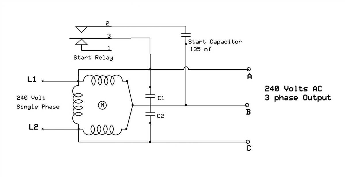
1. Star Connection (Y Connection): In this configuration, the three windings of the motor are connected together at one end, forming a star shape. The other ends of the windings are connected to the three phases of the power supply. This configuration is commonly used in motors that require a higher starting torque and lower current draw.
2. Delta Connection (Δ Connection): In this configuration, the three windings of the motor are connected in a closed loop, forming a triangle or delta shape. The phases of the power supply are connected to the corners of the triangle. This configuration is commonly used in motors that require a higher running torque and higher current draw.
3. Wye-Delta Connection (Y-Δ Connection): This configuration combines both the star and delta connections. The motor is connected in a star configuration during the starting period, and then switches to a delta configuration during the running period. This allows the motor to have a higher starting torque and lower current draw during startup, and then operate more efficiently in the delta configuration during normal operation.
These are just a few of the common wiring configurations for a 480 volt 3 phase motor. The specific configuration to use will depend on the motor’s requirements and the needs of the application. It’s important to consult the motor’s wiring diagram and follow the manufacturer’s instructions for proper installation and wiring.
In summary, understanding the different wiring configurations for a 480 volt 3 phase motor is essential for ensuring the motor operates safely and efficiently. Whether it’s a star connection, delta connection, or a combination of the two, choosing the right configuration can make a significant difference in the motor’s performance.
Step-by-Step Guide to Wiring a 480 Volt 3 Phase Motor
Wiring a 480-volt, 3-phase motor requires careful planning and attention to detail to ensure safe and efficient operation. Follow these step-by-step instructions to ensure proper wiring:
- Verify the motor voltage: Before starting the wiring process, it is crucial to confirm that the motor is designed to operate at 480 volts. Check the motor nameplate or manufacturer’s documentation to ensure compatibility.
- Prepare the electrical panel: The first step is to ensure that the electrical panel is suitable for handling 480-volt, 3-phase power. Verify that the panel has the appropriate voltage rating and sufficient amperage capacity to handle the motor’s power requirements.
- Plan the wiring layout: Carefully plan the wiring layout to minimize the distance and number of connections between the electrical panel and the motor. This will help reduce voltage drop and ensure efficient power delivery.
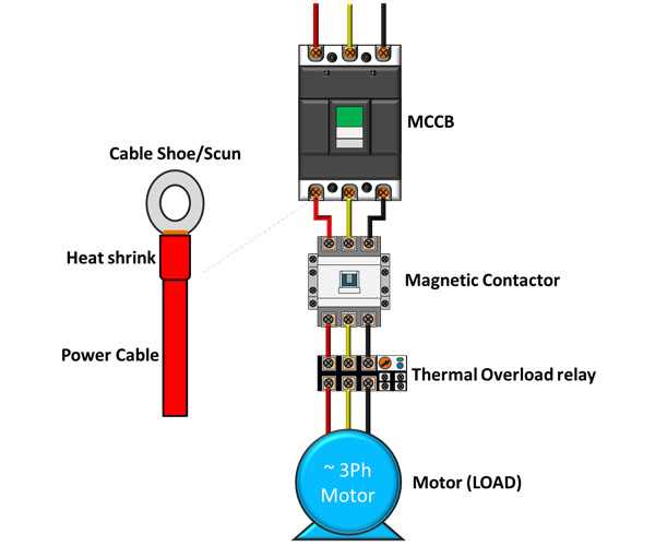
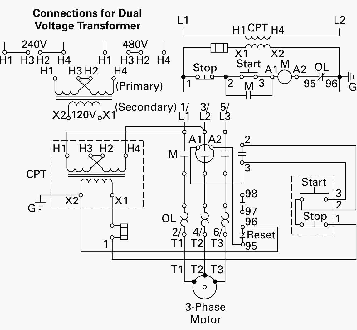
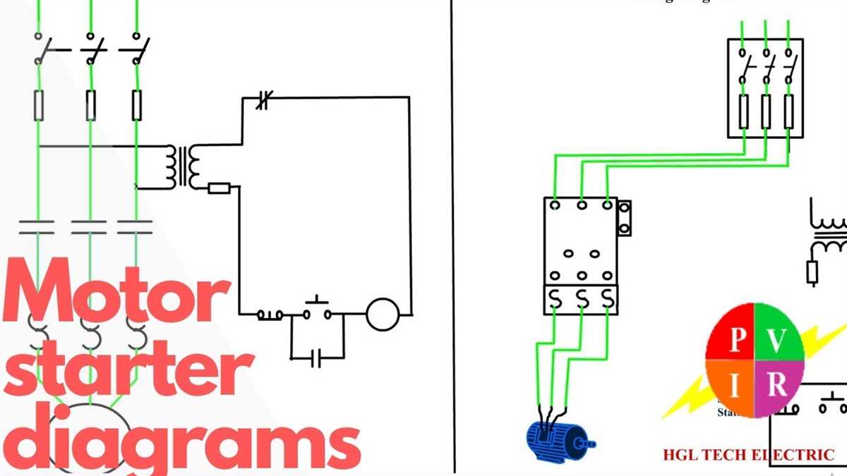
- Install the motor starter: Begin by installing a motor starter, which consists of a contactor and overload protection. The motor starter is used to control the motor’s operation and to provide necessary protection against overcurrent and motor overload.
- Connect the power supply: Run individual wires from the electrical panel to the motor starter. Connect the power supply wires to the line terminals of the motor starter, ensuring proper phase sequence (e.g., L1 to L1, L2 to L2, L3 to L3).
- Connect the motor leads: Connect the motor leads to the load terminals of the motor starter. Again, ensure the correct phase sequence and tighten all connections securely to prevent loose or faulty connections.
- Install control circuit wiring: Install the necessary control circuit wiring to enable the motor to be started and stopped remotely. This may include connecting push buttons, control relays, and other control devices to the control terminals of the motor starter.
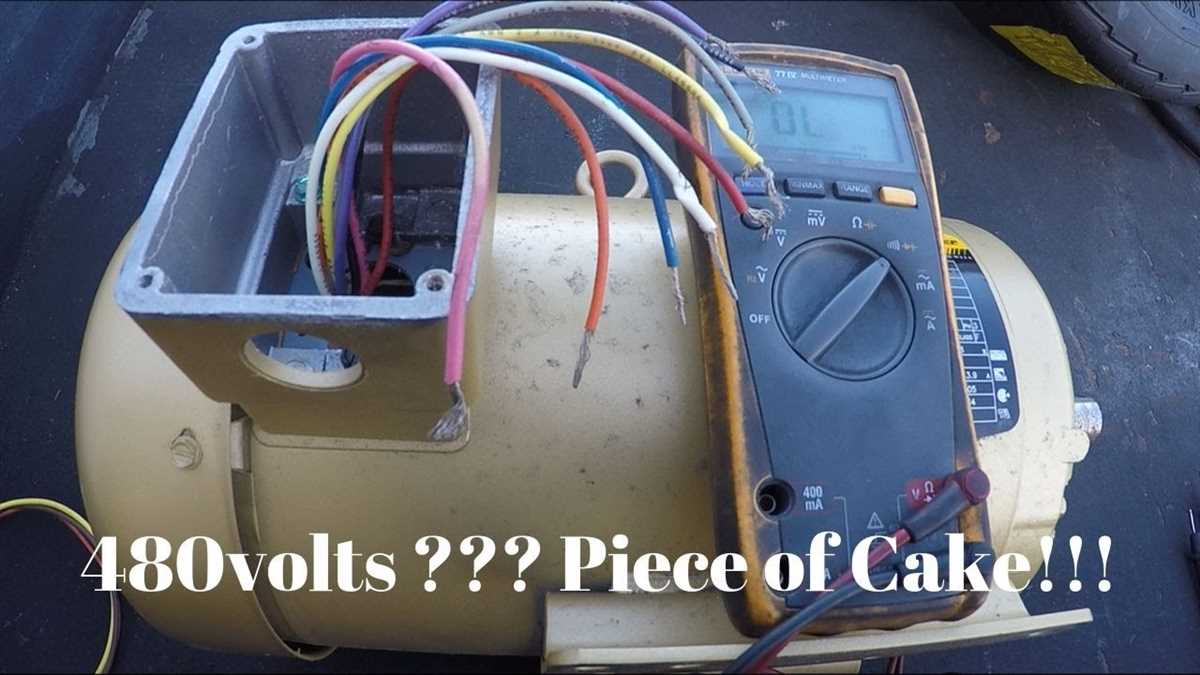
- Test the wiring: After completing the wiring, carefully inspect all connections for integrity and proper termination. Test the circuit using a multimeter to ensure voltage readings within the expected range. Verify that the motor starts, stops, and runs smoothly when controlled from the remote devices.
Following these step-by-step instructions will help ensure a safe and successful wiring process for a 480-volt, 3-phase motor. It is always recommended to consult the motor manufacturer’s documentation and local electrical codes for specific requirements and guidelines.
Troubleshooting and Maintenance Tips for 480 Volt 3 Phase Motor Wiring
In this article, we have discussed the wiring diagram for a 480 volt 3 phase motor and the steps involved in its installation. However, even with proper installation, occasional issues may arise, requiring troubleshooting and maintenance. Here are some tips to help you identify and address common problems:
1. Check for Loose Connections
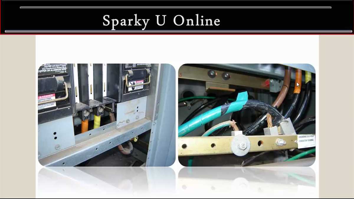
One of the most common issues with any electrical system is loose connections. Over time, vibrations can cause connections to become loose, resulting in poor electrical contact, increased resistance, and potential overheating. Regularly inspect all wiring connections in your motor system and tighten any loose connections to ensure proper contact and minimize the risk of electrical issues.
2. Inspect for Broken or Damaged Wires
Wires can get damaged due to various reasons, such as physical stress, exposure to extreme temperatures, or contact with corrosive substances. Regularly inspect all wire insulation for signs of damage, including cracks, fraying, or melting. If you find any damaged wires, replace them immediately to prevent electrical malfunctions or short circuits.
3. Test and Replace Faulty Components
If your motor is not functioning properly, it could be due to a faulty component, such as a capacitor or a starter. Use a multimeter or other appropriate testing equipment to check the continuity and voltage across these components. If any component fails the test, replace it with a new one to restore the motor’s operation.
4. Clean and Lubricate Moving Parts
A 480 volt 3 phase motor may have various moving parts, such as bearings and gears. Over time, these parts can accumulate dirt, dust, or grease, leading to increased friction, reduced efficiency, and potential motor failure. Regularly clean and lubricate these moving parts according to the manufacturer’s recommendations to ensure smooth operation and prolong the motor’s lifespan.
5. Consult a Professional Electrician
If you encounter complex electrical issues or are unsure about any aspect of troubleshooting and maintenance, it’s always best to consult a professional electrician. They have the knowledge, experience, and tools to diagnose and resolve electrical problems safely and efficiently. Attempting complex repairs without proper expertise can lead to further damage or injury.
By following these troubleshooting and maintenance tips, you can ensure the reliable and efficient operation of your 480 volt 3 phase motor. Regular inspections, proper maintenance, and timely repairs can help prevent costly downtime and extend the motor’s lifespan.