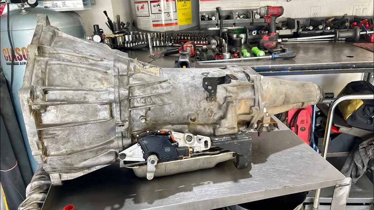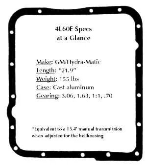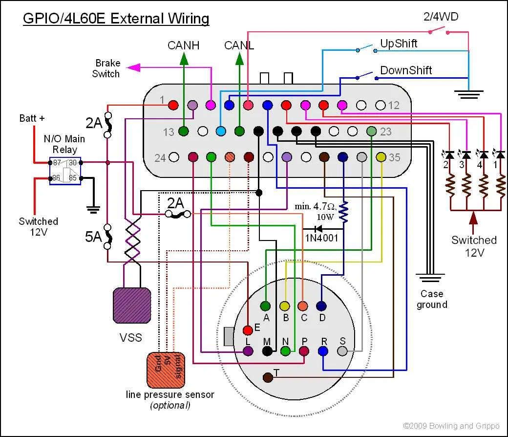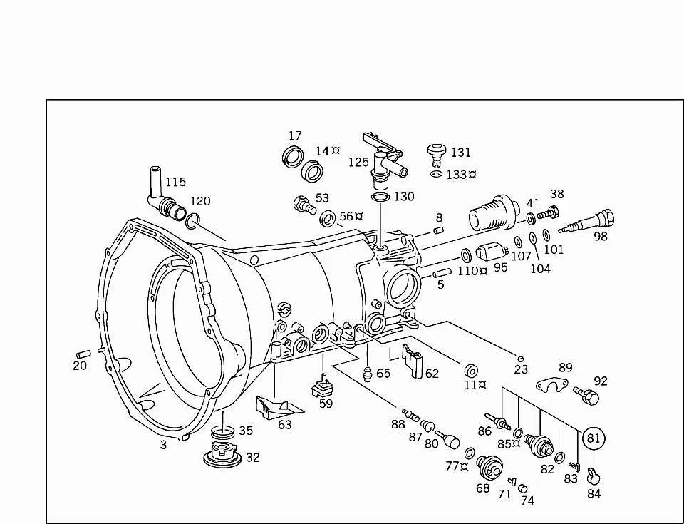
Begin by checking the valve body assembly. This is the central control hub, directing hydraulic pressure to engage specific gears. Look for worn gaskets, sticking solenoids, or clogged passages–each can cause erratic shifts or failure to engage drive.
Next, focus on the input and output shafts. These rotating elements transfer torque and are prone to wear at splines and bearings. Use a micrometer to verify tolerances; even minor deviations can result in vibration or premature wear.
Inspect the clutch packs and bands. These friction elements handle gear changes and often degrade under high load or poor fluid maintenance. Replace any that show discoloration, glazing, or reduced thickness.
The planetary gear sets are crucial for gear ratio changes. Examine each pinion and carrier for cracks, chipped teeth, or metal debris. Even minor damage here can cascade into larger mechanical failures.
Don’t overlook the pump assembly. Responsible for maintaining fluid pressure, it must be free from scoring or cavitation. Low pressure can cause delayed engagement or slipping in forward or reverse ranges.
4L60E Transmission Parts Diagram

Begin by identifying the valve body on the passenger side–remove the oil pan and filter to gain direct access. Inspect the solenoid cluster near the rear; these components are color-coded and labeled (e.g., 1-2 shift, 3-4 shift) for accurate placement.
- Valve Body: Central control unit for fluid routing. Ensure check balls are positioned correctly–there are typically seven, with specific seat locations.
- Separator Plate: Sits between the valve assembly and the case. Look for gasket damage or missing screens that may cause hydraulic leaks.
- Input Drum: Contains the forward and 3-4 clutch packs. Replace worn frictions and steels; measure clearance with a feeler gauge to confirm spec (usually 0.060″–0.100″).
- Sun Shell: Connects to the planetary set. Common failure point–check for cracks around the spline hub or stripped teeth.
- Planetary Gear Sets: Two sets–front and rear. Count the pinions (typically four in front, five in rear) to verify model compatibility.
- Servo Assembly: Located near the case side; includes cover, piston, and return spring. Replace D-ring seals if excessive fluid loss is present.
Reassembly requires aligning the pump rotor and stator support precisely; failure to seat the torque converter properly may result in immediate damage. Always refer to OE torque specs for bolts (e.g., pump cover bolts: 18 ft-lbs, valve body bolts: 97 in-lbs).
Visual Breakdown of Internal Components and Gear Sets

Start with identifying the pump assembly located directly behind the torque converter. This unit houses the rotor, vanes, and slide–crucial for maintaining hydraulic pressure. Inspect for wear on the vane tips and scoring inside the pump cavity.
Input drum follows, containing the forward and 3-4 clutch packs. Count the number of friction plates and steels to confirm OEM spec–typically 5 or 6 for forward, and 6 to 7 for 3-4. Replace any burnt or discolored friction material immediately.
The sun gear shell, often called the reaction shell, connects to the output shaft via the rear ring gear. Look for cracks around the neck or stripped splines. Use a hardened shell variant like “Beast” for durability in high-load applications.
Next, examine the planetary assemblies. The front unit includes a 5-pinion gearset in later models, improving torque capacity. Rear planetaries should rotate smoothly without gear lash. Replace any damaged needle bearings between pinions.
The low-reverse clutch pack sits in the case’s rear section. It engages via the low/reverse piston. Check for broken return springs and inspect the sealing rings for cuts or distortion.
Conclude with the band and servo system. The 2-4 band wraps around the reverse input drum, activated by the servo. Upgrade to a wider band and a high-performance servo (e.g., Corvette or Sonnax) for firmer engagement and longer lifespan.
Identification of Valve Body Elements in 4L60E Transmission

Start by locating the separator plate, a thin steel sheet placed between the upper and lower halves of the hydraulic assembly. It serves as the mounting surface for check balls and regulates fluid routing between channels.
Next, identify the shift solenoids. Two primary ones, labeled A and B, are located on the lower portion of the assembly. These are cylindrical, black plastic components with electrical connectors, typically mounted with a single bolt each.
The pressure control solenoid is positioned near the accumulator valve. It is larger than the shift solenoids and has a distinct silver body with a wire harness clip. This component directly influences line pressure based on throttle position.
Manual valve identification is crucial. It is linked to the manual shaft and moves in direct response to the gear selector. Look for a slotted metal rod seated in a guide at the end of the casting. Verify freedom of movement and alignment.
Check for the EPC (Electronic Pressure Control) circuit board near the center, secured by multiple Torx screws. This component interfaces with the solenoids and sensors to ensure precise modulation of pressure and timing.
Lastly, inspect the TCC (Torque Converter Clutch) solenoid. This unit is smaller, often attached to the pump cover side, and controls converter lock-up function. It is essential for efficient high-speed operation and fuel economy.
Pinpointing Common Wear Areas Using the 4L60E Parts Diagram
Focus inspection first on the valve body–specifically the TCC regulator valve bore. Excessive clearance here often leads to converter clutch slippage. Use a vacuum test or bore gauge to verify wear beyond factory tolerances.
Next, examine the input drum’s splines and clutch housing for heat discoloration and metal fatigue. These areas are prone to stress fractures, especially under high mileage or heavy load conditions. Replace the drum if bluing or hairline cracks are visible.
Check the reaction sun gear bushing for scoring or misalignment. Premature wear in this location typically results in noise during acceleration. A worn bushing also indicates possible contamination in the lubrication circuit.
Scrutinize the low/reverse clutch pack for uneven friction material wear. If clutch plates show coning or excessive glazing, suspect improper band adjustment or delayed engagement symptoms. Replace all affected discs, not just the damaged ones.
Inspect the pump rotor and slide for cavitation damage or galling. A compromised rotor face often causes low line pressure and delayed shifts. Measure rotor height and width against OEM specs to confirm serviceability.
Evaluate the 2-4 servo pin and bore for scoring or binding. Loss of intermediate clutch apply pressure often traces back to leakage here. A stepped or oversized pin may restore correct function if the bore is only lightly worn.