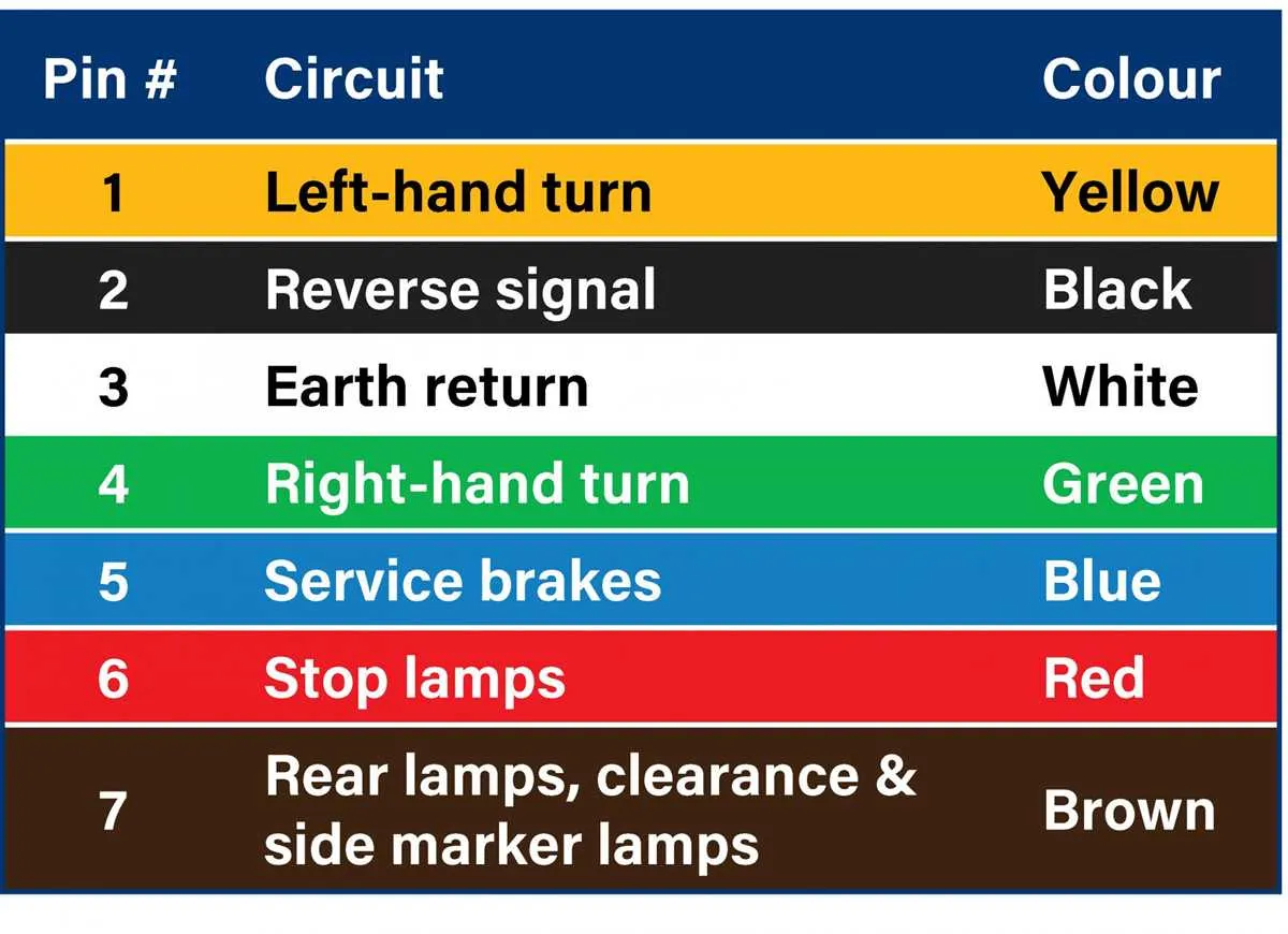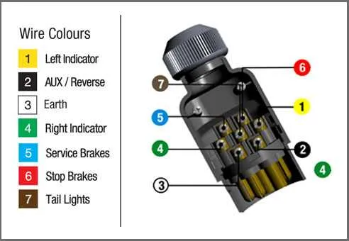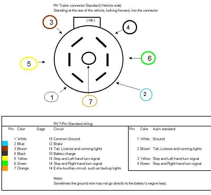
To properly link a 5-terminal system to a 7-terminal configuration, start by ensuring each lead from the source is correctly mapped to the corresponding connector on the new setup. Begin with the ground, typically the white cable, which should be connected to the appropriate grounding point on the 7-terminal system.
Second, connect the brake lights or signal system (usually the yellow or green wire) to the correct terminal. Verify that the remaining wires, such as those for the reverse and auxiliary functions, follow the proper sequence as outlined in your reference chart.
Lastly, always double-check that the power distribution terminals are linked properly to avoid any malfunction. Ensure all connections are secure to prevent wiring issues while in use.
Connecting 5-Terminal to 7-Terminal System

For proper conversion between a 5-terminal and 7-terminal configuration, follow these key steps:
- Identify the function of each terminal in both systems: ground, left turn signal, right turn signal, brake lights, and auxiliary connections.
- Connect the ground terminal of the 5-terminal system to the appropriate ground terminal in the 7-terminal system.
- Link the left and right turn signal terminals from the 5-terminal setup to the respective terminals on the 7-terminal connector.
- Ensure that the brake light and auxiliary terminals match correctly between the two systems to ensure proper functionality.
- Double-check for any unused terminals in the 7-terminal setup that aren’t required by your 5-terminal system.
Make sure all connections are tightly secured to prevent any disruptions during use. Testing the setup before regular usage ensures that all signals and lighting functions operate as expected.
Understanding the Connector Configuration
To ensure proper connection, make sure that each contact corresponds to its intended function. The first slot should handle the ground, providing a stable path for the return current. The second slot is designated for the left turn signal, while the third one connects to the right turn signal. The fourth slot is often used for the tail light, ensuring illumination when necessary.
For brake lights, the fifth slot is essential. It should be clearly identified to avoid confusion, as it carries the brake signal. Additionally, the sixth slot is commonly reserved for the auxiliary power supply, allowing an additional power source for any accessories or equipment. The seventh slot is critical for the electric brake, allowing precise control for safe braking.
Ensure all slots are securely attached, and verify that no short circuits are present before use. If in doubt, consult the relevant documentation for your specific setup to double-check the configuration.
How to Connect 5-Conductor System to 7-Connector Setup
Start by identifying the five necessary connections on the existing system. Connect the ground (often white) to the center terminal of the seven-slot connector. Next, connect the left turn signal (usually yellow) to the designated slot for this function. Follow with the right turn signal (green) to the corresponding position on the connector.
For the brake lights, the red conductor should be routed to the terminal designated for braking. Then, attach the running lights (brown wire) to the correct terminal for auxiliary illumination.
Ensure that all connections are secure, using appropriate connectors to avoid corrosion or disconnection. Test the setup thoroughly to confirm the system operates as expected, verifying each function, including turning, braking, and running lights.
Note: If additional features such as reverse lights or electric brakes are needed, additional wires must be run to the remaining slots on the connector.
Common Wiring Issues and Solutions

Ensure all connections are properly secured, as loose or corroded terminals are a common cause of electrical faults. Clean the contacts regularly and use dielectric grease to prevent oxidation.
Check for faulty ground connections. A poor ground can lead to intermittent electrical issues or complete failure of signals. Confirm that the ground point is clean and tightly fastened.
Inspect for short circuits, particularly in areas where the cables may rub against sharp edges or rough surfaces. Add protective sheathing or reroute the cables to avoid contact with potentially damaging points.
Verify the voltage compatibility between the vehicle and the connected system. Mismatched voltage can lead to malfunctioning lights or an overheated system. Use a multimeter to check the voltage at both ends of the connection.
When signals aren’t functioning correctly, test each wire individually to identify the faulty component. Swap out suspect parts and retest to confirm the issue is resolved.