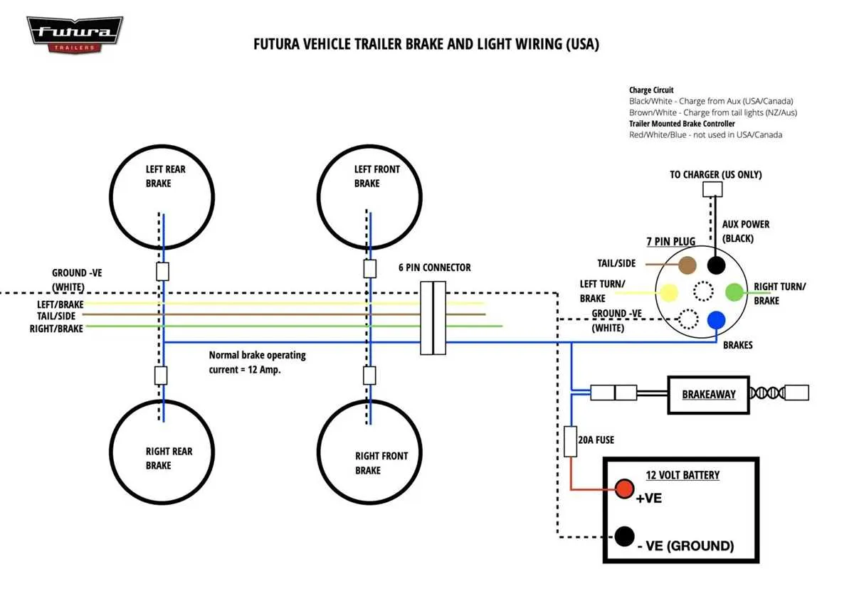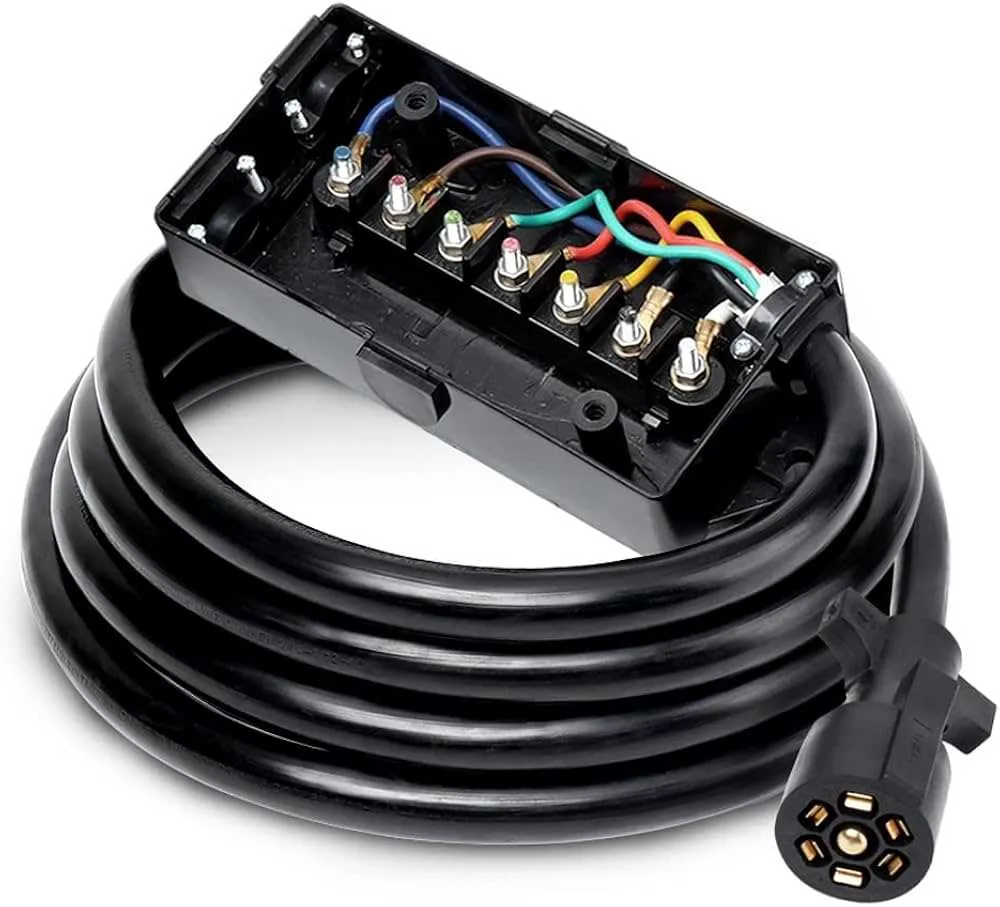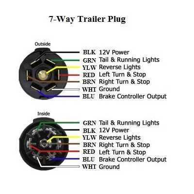
Start by ensuring that you have the correct tools and components for connecting the electrical system between your vehicle and the towed unit. A standard 7-pin connector is widely used for the job, as it allows the transmission of power, lights, and braking signals. Begin by identifying the color-coding scheme for the wiring. Most systems follow a standardized color-coding system for easy installation.
For the ground wire, use a white cable. This will provide a direct connection to the towing vehicle’s frame, ensuring proper grounding. For the brake signal, you’ll want a blue wire that activates the braking system when engaged. The left turn and right turn signals are typically managed by green and yellow wires, respectively.
Finally, make sure to double-check all connections before powering up the system. Securely attach each wire to the corresponding pin in the connector, and ensure that no wires are exposed or loosely connected. A proper connection is crucial for safe towing, preventing malfunctions in the lighting and braking systems during transit.
Wiring Setup for Secure Towing

Ensure a proper connection between the vehicle and the attached unit by following these guidelines. First, identify the main connectors: ground, tail, brake, and turn signals. The ground wire should be securely attached to the frame of the unit to avoid electrical malfunctions. Use a 4-pin or 7-pin connector depending on the lighting and brake system requirements of your unit.
For brake lights, use a dedicated wire to handle higher current, ensuring that the wire is thick enough to prevent overheating. The turn signal circuit should be separated to avoid interference with the brake lights, guaranteeing proper signaling functionality during maneuvers.
Confirm all connections are tightly secured with corrosion-resistant connectors. Regularly inspect the wiring for wear, fraying, or exposure to the elements. Consider using conduit or protective sleeves around the cables to protect them from abrasion and damage caused by the environment.
Understanding the Basic Electrical Configuration for Cargo Trailers
For a reliable electrical setup in a cargo hauler, ensure each component is correctly connected and insulated. Start with a ground connection, which must be securely attached to the frame, ensuring a safe path for the return current. Poor grounding can lead to malfunctioning lights and even potential electrical hazards.
The power supply line needs to be robust enough to handle the required current without overheating. Use a gauge wire that matches or exceeds the load of the lights and any other electrical accessories you plan to use. Typically, a 7-way plug is used to connect the power source to the cargo carrier.
For lighting, ensure the brake lights, turn signals, and tail lights are properly connected to the respective circuits. A typical setup involves color-coded wires to simplify the installation. For example, the yellow wire often connects to the left turn signal, while the green wire goes to the right side.
In addition, check the fuse protection to prevent overloading of the electrical system. Using the correct fuses can protect wiring from damage in case of a short circuit or other electrical issues.
Finally, always double-check your connections for tightness and corrosion. Loose connections can cause intermittent failures, while corrosion can lead to complete system failure. Regularly inspect the setup to ensure ongoing safety and performance.
Step-by-Step Guide for Wiring Tail Lights and Brake Lights

Ensure the proper functioning of your vehicle’s rear lighting system with these precise steps. Follow the instructions to connect tail and brake lights securely and efficiently.
- Identify the correct wire for the brake lights, typically marked with a brake signal or red color.
- Locate the ground wire and connect it to a metal surface on the vehicle’s frame. This is crucial for completing the circuit.
- Connect the running lights to the appropriate wire (often brown or yellow). Ensure the connections are secure and insulated to prevent short circuits.
- Test the brake light function by applying pressure to the brake pedal. Confirm that the lights illuminate and respond properly.
- Secure all wires using cable clips or ties to prevent them from moving or being exposed to heat or friction.
- Check all connections with a multimeter to ensure proper voltage is present across each light component. Adjust any loose connections as needed.
- After confirming all components are functioning, protect connections with electrical tape to prevent moisture and corrosion.
Regularly inspect the setup for signs of wear or damage. If any light fails to operate correctly, check the connection points and replace damaged wires promptly.
How to Troubleshoot Common Electrical Issues in Transport Units

First, check for loose connections. A frequent cause of malfunction is improperly secured terminals, which can cause intermittent power loss. Inspect each connector and ensure all are tight and corrosion-free. If you find any damage, replace or clean the connectors using dielectric grease to prevent future corrosion.
Next, test the ground connections. Poor grounding is another common issue that leads to faulty lighting or equipment failure. Ensure that all grounding points are clean, free of rust, and securely fastened to a bare metal surface. A weak or absent ground can disrupt current flow, leading to dim lights or no power at all.
Inspect the fuse box and circuit breakers for signs of failure. If a fuse blows or a breaker trips repeatedly, it could indicate a short or an overload. Replace any blown fuses and reset the breakers, but if the issue persists, further investigation into the affected circuit is necessary.
Check the voltage supply using a multimeter. Low voltage can cause dim lighting or malfunctioning equipment. Measure the voltage at different points, ensuring it matches the specifications of the electrical system. If the voltage is low, inspect the power source for issues or replace damaged cables that may be causing a drop in current.
Finally, verify the integrity of the cables. Frayed or damaged wires can lead to electrical shorts or power loss. Run a visual inspection of all cables for signs of wear, cuts, or abrasions. Any damaged wires should be replaced to prevent further electrical issues.