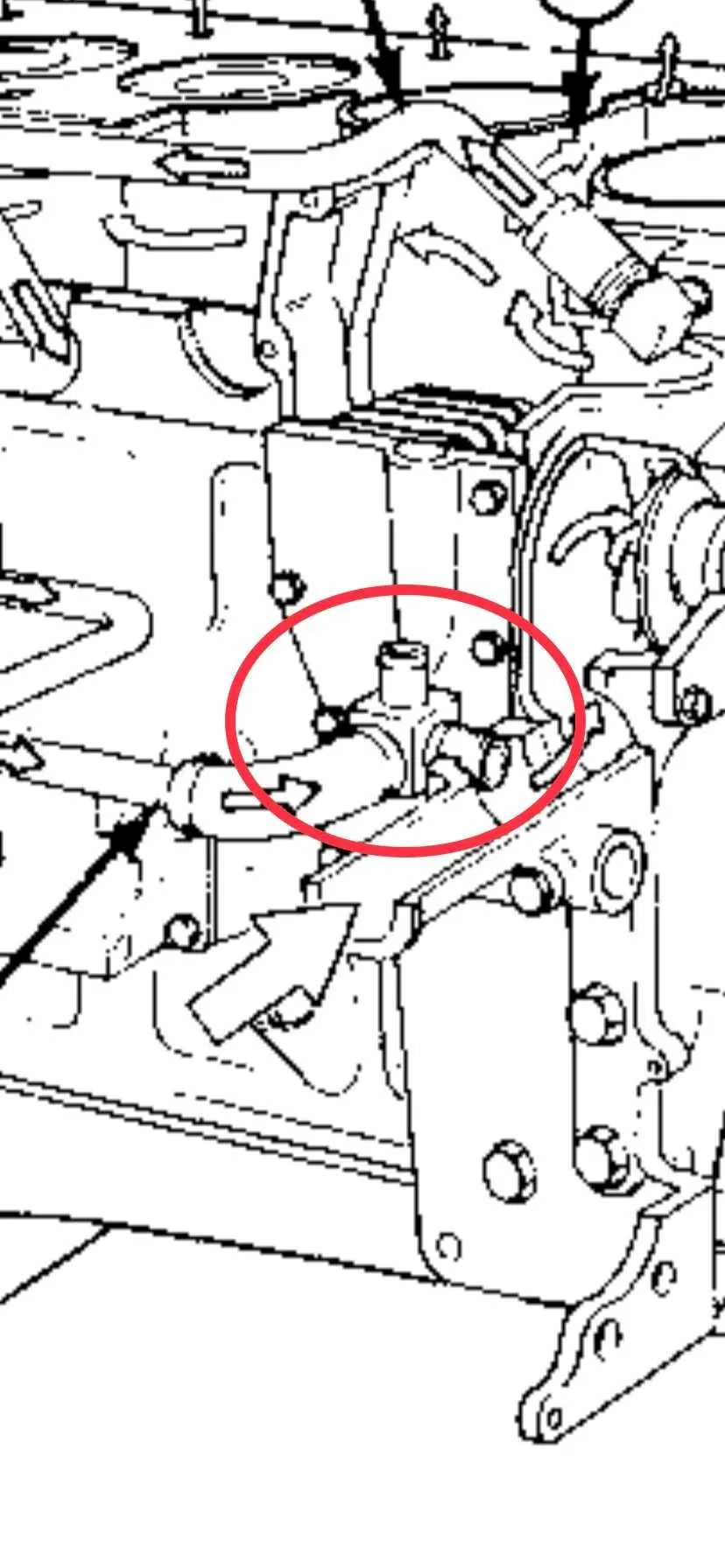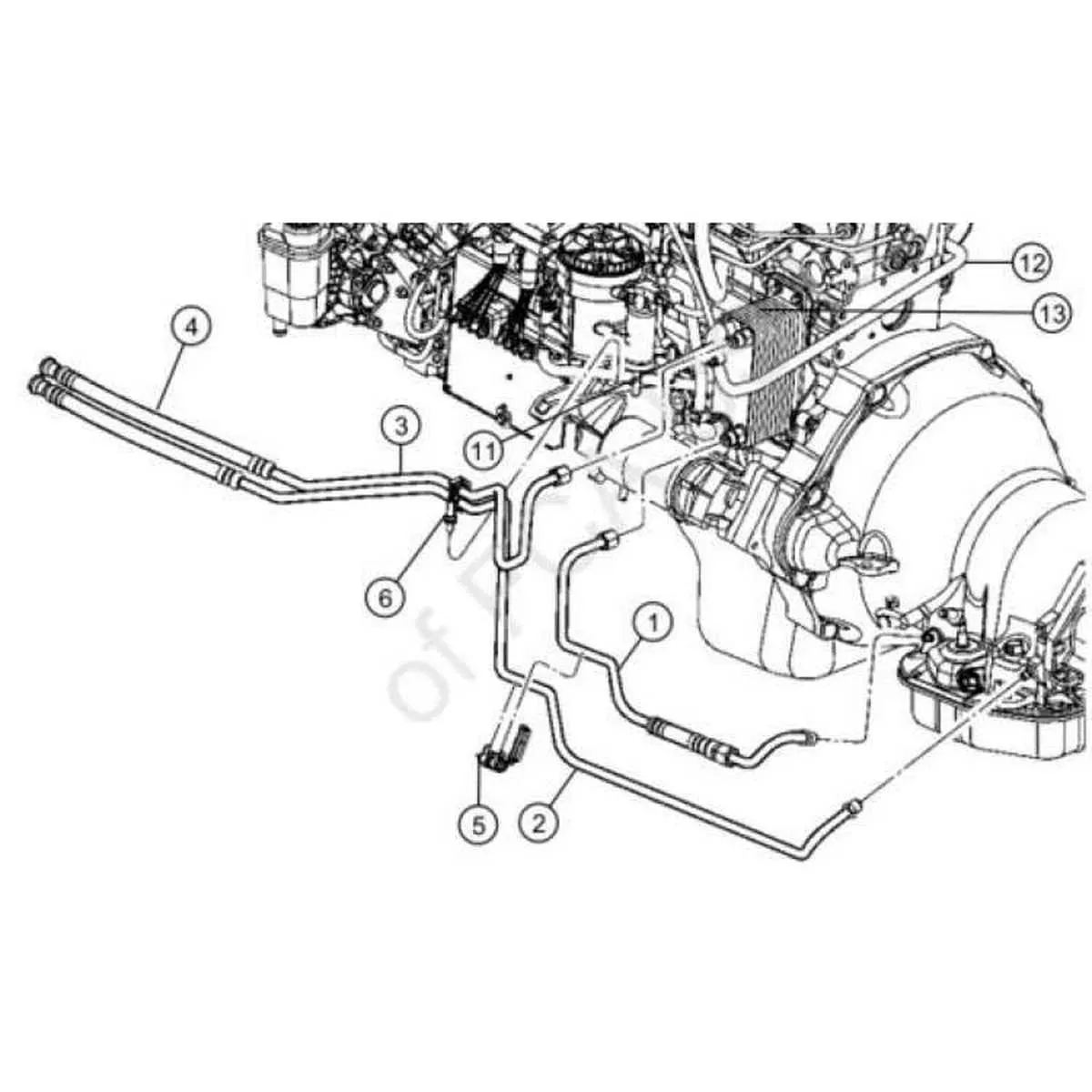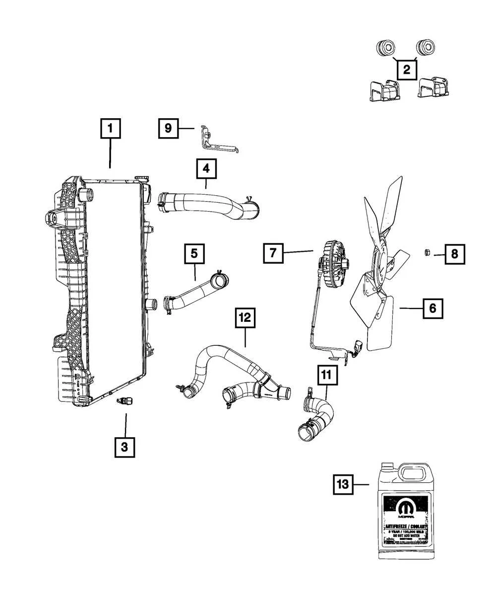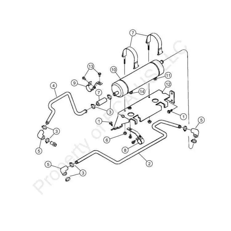
When working with the engine’s liquid circulation system, it’s essential to pay close attention to the layout of all connecting pipes. These are responsible for maintaining optimal temperatures within critical components by efficiently circulating the coolant throughout the engine block and surrounding systems. Proper installation is crucial for preventing overheating and ensuring long-term engine performance.
First and foremost, ensure that each connection is tightly sealed and that the paths are free from obstruction or damage. If any component shows signs of wear, immediate replacement is necessary to avoid leaks or system failure. The correct positioning of each pipe is key to maintaining smooth operation.
Additionally, be cautious when handling connections near high-heat areas, such as the engine block or exhaust manifolds. Excessive heat can degrade the materials, leading to cracks or failures over time. Always verify that all clamps and fittings are in place and properly tightened to secure the network of tubes without causing stress or bending.
When assembling, follow the factory specifications to ensure the pipes are connected in the right order, matching the intended flow of fluid through the system. This ensures even distribution and prevents hot spots from forming, which can cause overheating or component damage. Regular inspections and maintenance are recommended to keep everything in peak condition.
Cooling System Pipe Routing

Ensure the proper routing of the engine’s liquid circulation system for optimal performance. The upper and lower connections must align correctly to prevent leaks or cooling inefficiencies. Always use hoses rated for high temperature and pressure tolerance.
Tip: Pay close attention to the connection points around the thermostat and water pump. These are high-stress areas where wear is most likely. Ensure the seals are intact and there are no kinks or twists in the tubing.
Note: If replacing sections of the liquid circulation system, check for cracks or weaknesses in the material. When in doubt, replace parts before they fail, especially in areas exposed to constant temperature fluctuations.
Understanding the Key Hoses in the Engine Cooling System

Ensure the proper flow of coolant through your engine by focusing on the key tubes and connections within the system. Proper maintenance of these components helps avoid overheating and ensures efficient operation.
- Upper Radiator Tube: This part is responsible for carrying coolant from the engine block to the radiator for cooling. Regular inspection is crucial for checking any signs of wear or cracks.
- Lower Radiator Tube: Once the coolant is cooled in the radiator, this tube returns it to the engine. Leaks in this area can lead to pressure loss, so it’s vital to check for any signs of degradation.
- Bypass Line: Facilitates coolant circulation when the engine is cold. This ensures the temperature reaches optimal levels more quickly. Blockages or leaks in this tube can prevent the engine from reaching proper operating temperature.
- Heater Core Lines: Carry the heated fluid into the cabin for climate control. If you notice a decrease in cabin heat, inspect these lines for any obstructions or leaks.
- Coolant Return Line: This carries the fluid back from various engine components for re-circulation. Ensure it is securely fastened to prevent leakage or wear.
Regularly inspect these components for signs of cracking, leaks, or brittleness. Any issue with these parts could result in system inefficiency or failure. It’s also recommended to flush and replace the fluid regularly to maintain optimal performance of these components.
Step-by-Step Guide to Properly Routing Fluid Transfer Hoses
1. Identify Key Connection Points: Begin by locating all primary inlets and outlets for the engine’s circulation system. These are typically positioned near the engine block, radiator, and water pump. Ensure each attachment site is clean and free of debris before starting the routing process.
2. Use the Correct Length of Tubing: Select hoses that fit the necessary distances between connection points without tension. Tubes should not be stretched or compressed excessively. Measure the required length carefully, leaving enough slack for natural movement without causing kinks.
3. Follow Engine Block Pathways: Route the tubing along pre-existing channels or protected paths in the engine compartment. Avoid sharp bends and tight corners, as these can restrict fluid flow and increase the risk of wear.
4. Secure with Clamps: Ensure each connection is fastened tightly with durable, corrosion-resistant clamps. The clamps should be positioned evenly along the tube’s circumference, preventing any air pockets or leaks. Recheck the tightness after completing the routing.
5. Ensure Proper Insulation: Where the tubing comes into contact with high-heat components, such as the exhaust manifold, use heat-resistant sleeves or wraps. This will prevent premature degradation of the material and maintain the integrity of the fluid transfer system.
6. Double-Check for Clearance: After completing the routing, check that the hoses do not interfere with moving engine parts like belts or pulleys. A slight misalignment can cause friction, wear, or even rupture over time.
7. Test the System: Once the hoses are routed and secured, run the engine to verify that fluid circulates properly. Look for any signs of leakage at the connection points. If necessary, adjust the positioning of the hoses for better alignment or fluid flow efficiency.
Common Issues and Troubleshooting Tips for Coolant Circuit Layouts

One of the most frequent issues in coolant systems is the improper routing of fluid channels, leading to leaks or poor fluid circulation. Ensure that all paths are securely connected, as even a small gap can lead to significant pressure loss.
If there is persistent overheating or inconsistent temperature readings, inspect the connections between the fluid channels and pumps. A common cause is air pockets trapped within the system, which can be resolved by carefully bleeding the system, removing any trapped air.
Another issue to look out for is the wear and tear on rubber seals and connectors over time. As the system ages, these materials can become brittle, causing cracks and fluid loss. Regularly check the condition of all seals and replace them as needed to avoid leaks.
| Issue | Cause | Solution |
|---|---|---|
| Fluid Leaks | Loose connections or damaged seals | Tighten connections and replace seals |
| Overheating | Air pockets, restricted flow | Bleed system and check for blockages |
| Inconsistent Temperature | Faulty sensor or pump | Test sensor functionality and inspect pump |
If you experience inconsistent pressure or difficulty maintaining a stable temperature, consider the possibility of a malfunctioning pump or thermostat. Test these components to ensure they are working within the specified parameters.