
When it comes to measuring weight or force, load cells are essential components. They can be found in various applications, from industrial scales to medical equipment. One type of load cell that is commonly used is the 6-wire load cell. In this article, we will delve into the details of the 6-wire load cell wiring diagram, explaining how it works and its advantages over other load cell configurations.
The 6-wire load cell is known for its superior accuracy and precision. It achieves this by using two additional sense wires in addition to the traditional four-wire configuration. These sense wires compensate for changes in the resistance of the excitation and signal wires, resulting in more accurate measurements. This makes 6-wire load cells ideal for applications that require high precision and reliability.
In a 6-wire load cell wiring diagram, the sense wires are connected to the respective excitation and signal wires. This allows the load cell to measure and compensate for any resistance changes in the circuit. The use of sense wires also reduces the effects of temperature variations and cable length on the measurement accuracy.
Overall, the 6-wire load cell wiring diagram provides a more accurate and stable measurement compared to other load cell configurations. It is widely used in industries such as aerospace, automotive, and manufacturing where precise weight or force measurements are critical. By understanding the wiring diagram and its benefits, engineers and technicians can ensure optimal performance and reliability of load cell systems.
What is a 6 wire load cell?
A 6 wire load cell is a type of sensor commonly used in the field of engineering and automation. It is designed to measure force and weight by converting mechanical stress into electrical signals. The load cell consists of a strain gauge–an electrical resistor that changes its resistance when it is stretched or compressed–placed on a metal structure. By measuring the change in resistance, the load cell can accurately determine the applied force or weight.
Unlike traditional load cells that use 4 wires, a 6 wire load cell includes two additional wires for compensating the effects of temperature changes and cable resistance. These extra wires help to eliminate any errors caused by variations in temperature or resistance, improving the accuracy and reliability of the measurements.
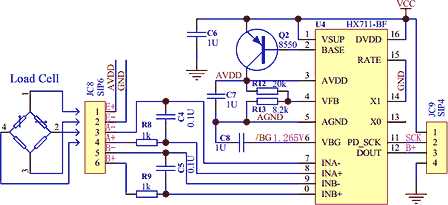
Typically, the six wires are connected to a Wheatstone bridge circuit, which is a popular circuit configuration for measuring small changes in resistance. The Wheatstone bridge allows for precise measurement and compensates for any changes in temperature or cable resistance, delivering highly accurate and stable readings.
6 wire load cells are commonly used in various applications such as industrial automation, robotics, aerospace, and weighing systems. Their high accuracy and reliability make them ideal for situations where precise measurements are required.
The importance of wiring in load cells
Wiring is a crucial aspect of load cells, which are devices used to measure weight or force. Proper wiring ensures accurate and reliable readings, while incorrect wiring can lead to erroneous measurements and potential safety hazards. Thus, it is essential to understand the wiring requirements of load cells and follow the correct wiring diagrams provided by the manufacturer.
Load cells typically consist of strain gauges that convert mechanical force into electrical signals. These strain gauges are connected to a Wheatstone bridge circuit, which balances the electrical output based on the applied force. The wiring of the load cell involves connecting the strain gauges and the Wheatstone bridge to the appropriate terminals of the measuring system or instrument.
Incorrect wiring can cause various problems. For example, the wrong wiring can introduce noise and interference into the measurement signal, leading to inaccurate readings. It can also result in incorrect calibration and poor linearity of the load cell. Additionally, improper wiring can potentially damage the load cell or the measuring instrument.
To avoid these issues, it is crucial to carefully follow the wiring diagram provided by the load cell manufacturer. The diagram specifies the wire colors and their corresponding terminals, ensuring the proper connection. Additionally, it is important to use high-quality wiring components that can withstand the operating conditions and provide reliable electrical connections.
In conclusion, wiring is an essential aspect of load cells and plays a crucial role in ensuring accurate and reliable measurements. Correct wiring eliminates potential measurement errors, interference, and damage to the load cell or measuring instrument. By following the wiring diagram provided by the manufacturer and using high-quality wiring components, users can optimize the performance and longevity of their load cell systems.
Understanding the Wiring Diagram
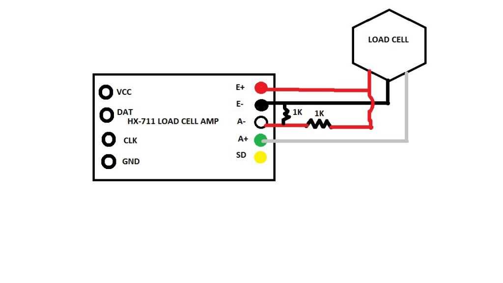
When working with a 6 wire load cell, understanding the wiring diagram is essential. The wiring diagram provides a visual representation of how the wires should be connected in order for the load cell to function properly. It shows the different terminals and their corresponding connections, allowing technicians to easily identify and troubleshoot any potential wiring issues.
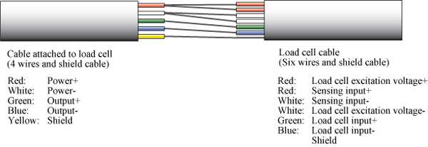
One key aspect of the wiring diagram is the color coding of the wires. Each wire is typically assigned a specific color to indicate its function. For example, the red wire may be designated as the excitation or power supply wire, while the black wire may be the ground wire. These color-coded connections help ensure that the load cell is wired correctly and that the electrical signals are transmitted accurately.
It is important to pay attention to the wiring diagram and follow it precisely, as any mistakes or improper connections can lead to inaccurate readings or even damage to the load cell.
Additionally, the wiring diagram may also include information on additional components that need to be connected, such as amplifiers or signal conditioners. These components play a crucial role in amplifying and conditioning the electrical signals from the load cell, ensuring accurate measurements and reliable data.
Overall, understanding the wiring diagram is crucial for proper installation and operation of a 6 wire load cell. By carefully studying and following the diagram, technicians can ensure that the load cell is wired correctly, allowing for accurate and precise measurements in various applications.
Proper wiring techniques for a 6 wire load cell
The excitation wires are responsible for supplying power to the load cell and are usually colored red, white, and black. The signal wires, on the other hand, carry the measurement data and are typically colored green, blue, and shielded wire. It is crucial to keep the signal wires separate from the excitation wires to avoid interference and ensure precise readings.
To wire a 6 wire load cell properly, follow these steps:
- Identify the excitation wires by their color coding or labeling provided with the load cell.
- Connect the red excitation wire to the positive terminal of the power supply.
- Connect the white excitation wire to the negative terminal of the power supply.
- Connect the black excitation wire to the load cell’s excitation (+Exc) terminal.
- Identify the signal wires by their color coding or labeling provided with the load cell.
- Connect the green signal wire to the load cell’s signal (+Sig) terminal.
- Connect the blue signal wire to the load cell’s signal (-Sig) terminal.
- Connect the shielded wire to the load cell’s shield (SHLD) terminal. The shielded wire helps to minimize electromagnetic interference.
By following these proper wiring techniques, you can ensure that your 6 wire load cell is correctly connected and ready to provide accurate and reliable measurements for your application.
Troubleshooting common wiring issues
When working with a 6-wire load cell, it’s essential to understand and troubleshoot any wiring issues that may arise. Here are some common problems you may encounter and their potential solutions:
1. Loose or incorrect wiring connections:
One of the most common issues is loose or incorrect wiring connections. Double-check all the connections to ensure they are secure and properly connected to the load cell and other components. Verify that the wiring follows the correct color coding.
2. Damaged or broken wires:
If the load cell is not working correctly, inspect the wiring for any signs of damage or breakage. Check the wires for cuts, frays, or breaks. If you find any damage, replace the affected wires with new ones and ensure they are securely connected.
3. Incorrect wiring configuration:
Another potential issue is an incorrect wiring configuration. Consult the load cell’s datasheet or manual to ensure you have connected the wires correctly. Any incorrect wiring configuration can lead to inaccurate readings or complete failure of the load cell.
4. Faulty components:
If all the wiring connections are correct, and there is no visible damage, the issue may lie with one of the components. Test each component individually to identify any faulty parts. Replace any faulty components to restore the load cell’s functionality.
5. Interference or noise:
In some cases, interference or noise can disrupt the load cell’s performance. Make sure the load cell is shielded from any electromagnetic interference sources. Additionally, ensure proper grounding techniques are followed to minimize electrical noise.
By addressing these common wiring issues, you can troubleshoot and resolve any problems with your 6-wire load cell. Remember to follow proper safety precautions when working with electrical components and consult the load cell’s manufacturer or technical support if you encounter any difficulties.