
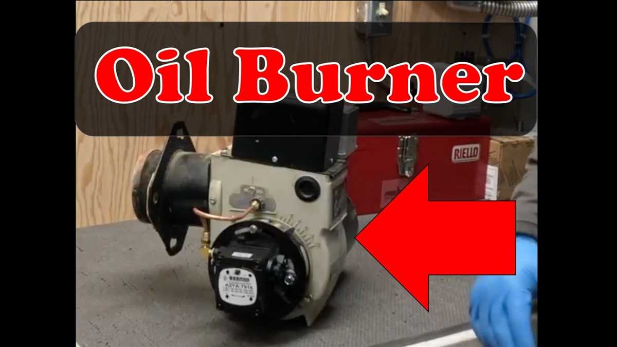
Beckett AFG oil burner is a popular choice for heating systems that use oil. The burner is known for its efficiency and reliability, delivering consistent heat to homes and buildings. To understand how the Beckett AFG oil burner works, it is helpful to refer to a parts diagram that illustrates the different components and their functions.
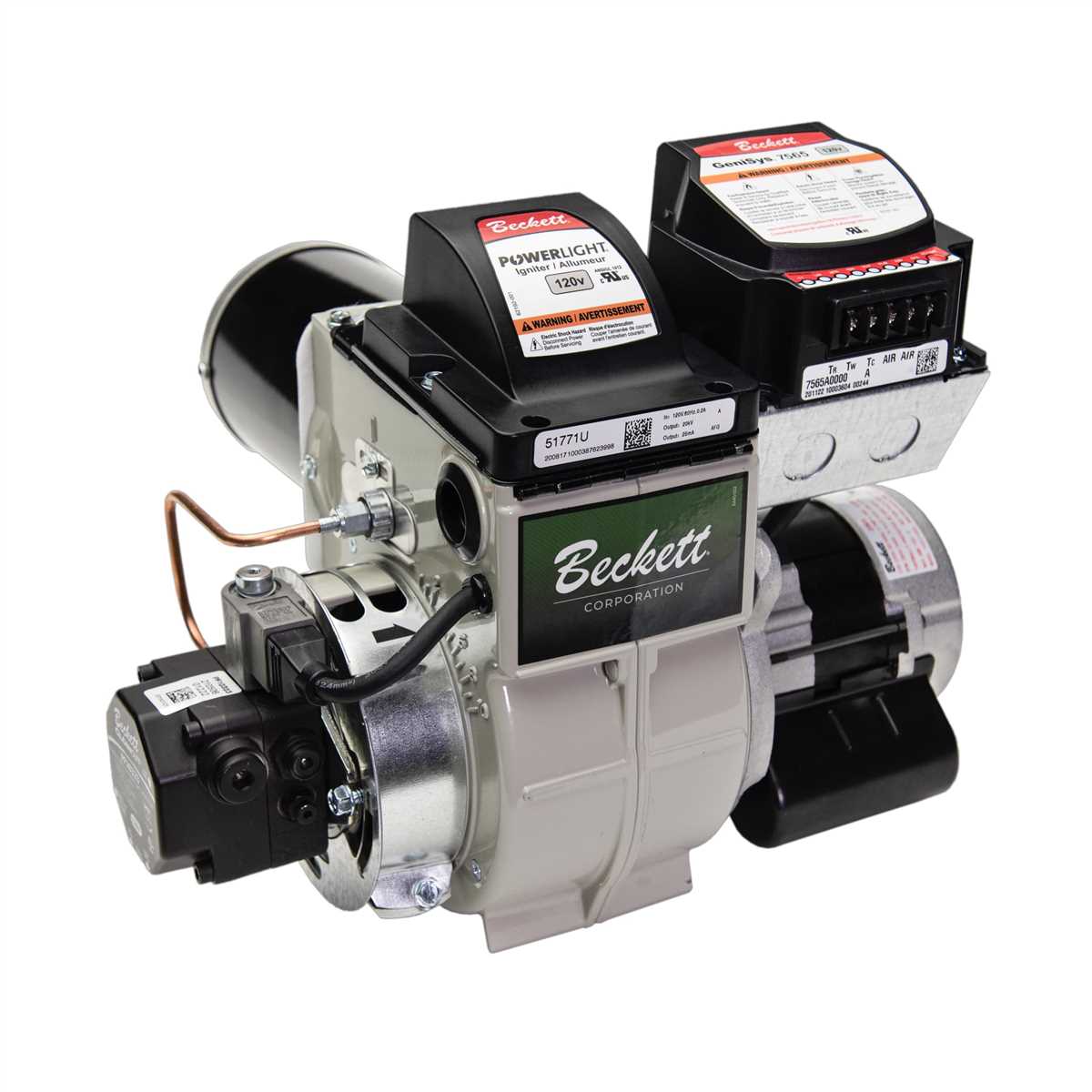
In the Beckett AFG oil burner parts diagram, you will see the main components such as the motor, ignition transformer, blower assembly, pump, and oil nozzle. The motor is responsible for running the burner, while the ignition transformer provides the spark that ignites the oil. The blower assembly ensures proper air flow, while the pump delivers the oil to the nozzle.
The oil nozzle is a critical part of the burner, as it atomizes the oil for efficient combustion. The burner also includes safety features such as the primary control and cad cell assembly, which monitor the flame and shut off the burner in case of any malfunctions. By understanding the different parts of the Beckett AFG oil burner, homeowners and technicians can effectively troubleshoot and maintain the burner for optimal performance.
Understanding the Beckett AFG Oil Burner Parts Diagram
The Beckett AFG oil burner is a commonly used component in oil heating systems. Understanding its parts and how they work together is crucial for proper maintenance and troubleshooting. By referring to the Beckett AFG oil burner parts diagram, you can easily identify each component and its function.
Main components:
- Nozzle: The nozzle is responsible for atomizing the oil and spraying it into the combustion chamber. It determines the fuel flow rate and pattern.
- Ignition Transformer: The ignition transformer provides the high voltage required to create a spark for ignition.
- Ignition Electrode: The ignition electrode creates a spark to ignite the oil-air mixture.
- Motor: The motor drives the oil pump and fan, providing the necessary air and fuel flow.
- Oil Pump: The oil pump is responsible for drawing fuel from the tank and supplying it to the nozzle.
- Fan: The fan provides the necessary air for combustion.
- Primary Control: The primary control is the brain of the burner, regulating the various functions and ensuring safe operation.
- Flame Sensor: The flame sensor detects the presence of a flame and sends a signal to the primary control for monitoring and safety purposes.
Understanding the Beckett AFG oil burner parts diagram allows technicians and homeowners to identify specific components and their roles in the overall system. This knowledge can be invaluable for troubleshooting and making necessary repairs or replacements. It is recommended to consult the manufacturer’s documentation or seek professional assistance when working with oil burners to ensure safety and proper operation.
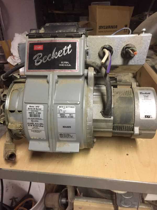
What is a Beckett AFG oil burner?
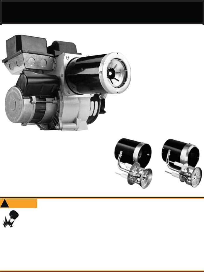
The Beckett AFG oil burner is a popular choice for heating systems that use oil as fuel. It is commonly used in residential and commercial buildings to provide heat and hot water. The AFG model is known for its efficiency, reliability, and ease of maintenance.
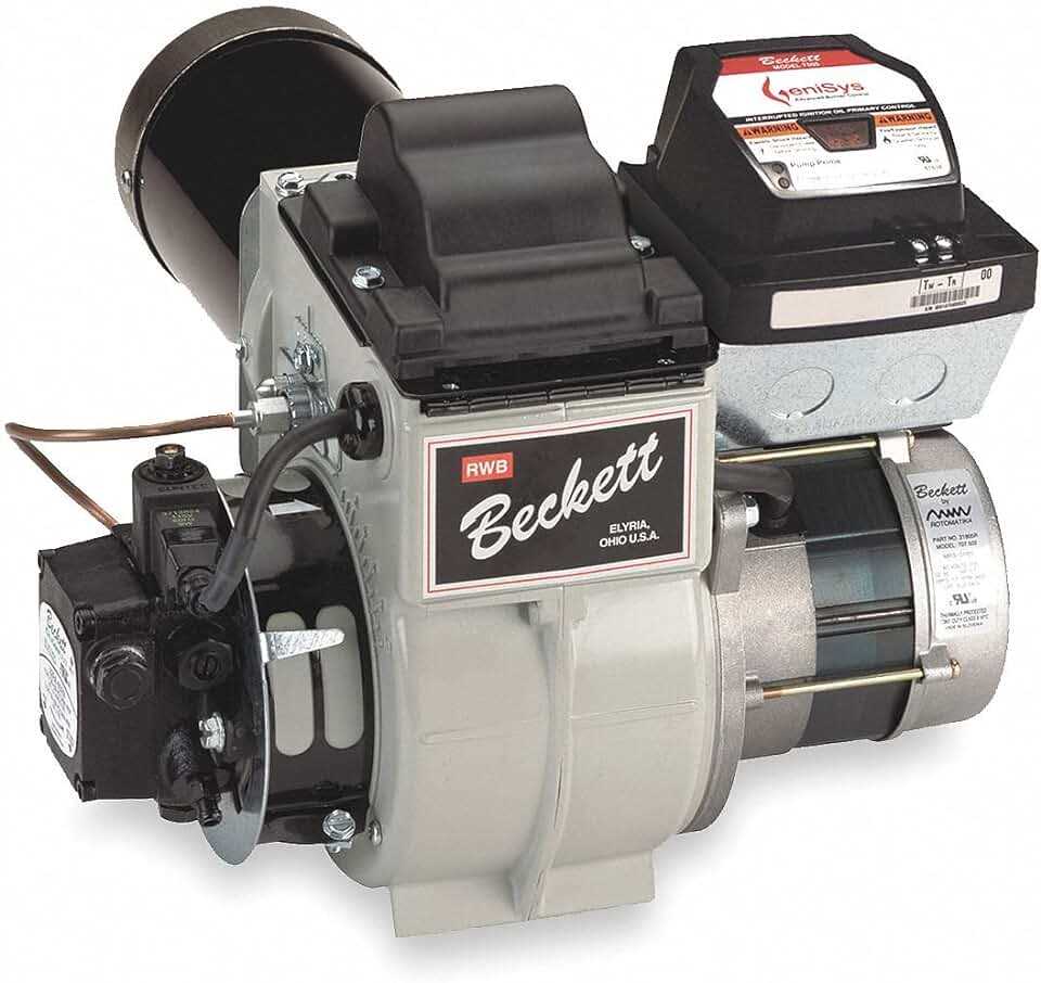
One of the key features of the Beckett AFG oil burner is its adjustable air shutter, which allows for precise control of the air-to-fuel ratio. This helps to optimize combustion and ensure clean and efficient operation. The burner also includes an electronic igniter for quick and reliable ignition.
The Beckett AFG oil burner is designed for easy installation and maintenance. It has a compact and durable construction, with a cast iron head and a heavy-duty motor. The burner is equipped with a solenoid valve for oil flow control, a flame retention head for improved combustion efficiency, and an oil preheater to ensure smooth ignition.
Overall, the Beckett AFG oil burner is a reliable and efficient choice for heating systems that rely on oil as fuel. Its adjustable air shutter, electronic igniter, and easy maintenance make it a popular option for residential and commercial applications. Whether you are looking to install a new oil heating system or replace an existing burner, the Beckett AFG oil burner is worth considering.
Key components of the Beckett AFG oil burner
The Beckett AFG oil burner is a commonly used component in heating systems that utilize oil as a fuel source. It is important to understand the key components of this burner in order to properly maintain and repair it. Some of the key components of the Beckett AFG oil burner include:
- Burner Motor: The burner motor is responsible for providing the necessary power to drive the fan and pump in the oil burner. It must be properly sized and maintained to ensure that it operates efficiently.
- Fuel Pump: The fuel pump is responsible for drawing oil from the oil tank and supplying it to the burner for combustion. It is a vital component of the Beckett AFG oil burner and must be regularly checked and serviced to ensure proper fuel delivery.
- Ignition Transformer: The ignition transformer is responsible for providing the high voltage spark that ignites the oil and air mixture in the burner. It must be properly calibrated and maintained to ensure reliable ignition.
- Combustion Chamber: The combustion chamber is where the oil and air mixture is ignited and burned. It is designed to provide efficient combustion and minimize the release of pollutants into the air.
- Solenoid Valve: The solenoid valve is responsible for controlling the flow of oil to the burner. It is typically operated by the thermostat or control system, opening and closing as needed to maintain the desired temperature.
Proper maintenance and regular inspections of these key components are essential for the efficient and reliable operation of the Beckett AFG oil burner. Any signs of wear or malfunction should be addressed promptly by a qualified technician to avoid further damage and ensure the safe functioning of the heating system.
Functions of each component
The Beckett AFG oil burner consists of several components, each with its specific function. Understanding the functions of these components is essential for proper operation and maintenance of the oil burner.
Nozzle
The nozzle is responsible for atomizing the oil into fine droplets, allowing for efficient combustion. It is a crucial component that determines the oil spray pattern and flow rate. The nozzle’s function is to deliver a precise amount of oil into the combustion chamber, ensuring a stable flame.
Pump
The pump is responsible for supplying oil under pressure to the nozzle. It draws oil from the fuel storage tank and pressurizes it, allowing for a controlled flow rate. The pump’s function is to ensure a consistent supply of oil to the nozzle, enabling efficient combustion and preventing flame instability.
Ignition System
The ignition system is responsible for igniting the oil-air mixture in the combustion chamber. It typically consists of an electrode and a transformer. The electrode produces a spark, while the transformer provides the necessary voltage. The ignition system’s function is to create a reliable spark that ignites the oil-air mixture, initiating the combustion process.
Control Box
The control box is the brain of the oil burner, responsible for regulating and monitoring its operation. It receives input from various sensors and controls the operation of the pump, ignition system, and other components. The control box’s function is to ensure optimal combustion, monitor safety parameters, and provide diagnostics in case of any malfunctions.
Flame Detector
The flame detector is a safety component that senses the presence of a flame in the combustion chamber. It typically uses a photoresistor or an ionization electrode. The flame detector’s function is to detect the flame and send a signal to the control box, which verifies the presence of a stable flame. If no flame is detected, the control box shuts down the oil burner to prevent fuel accumulation and potential hazards.
Air Intake
The air intake is responsible for supplying combustion air to the burner. It typically includes an air filter to remove any contaminants from the incoming air. The air intake’s function is to provide the necessary oxygen for combustion, ensuring efficient and clean burning of the oil.
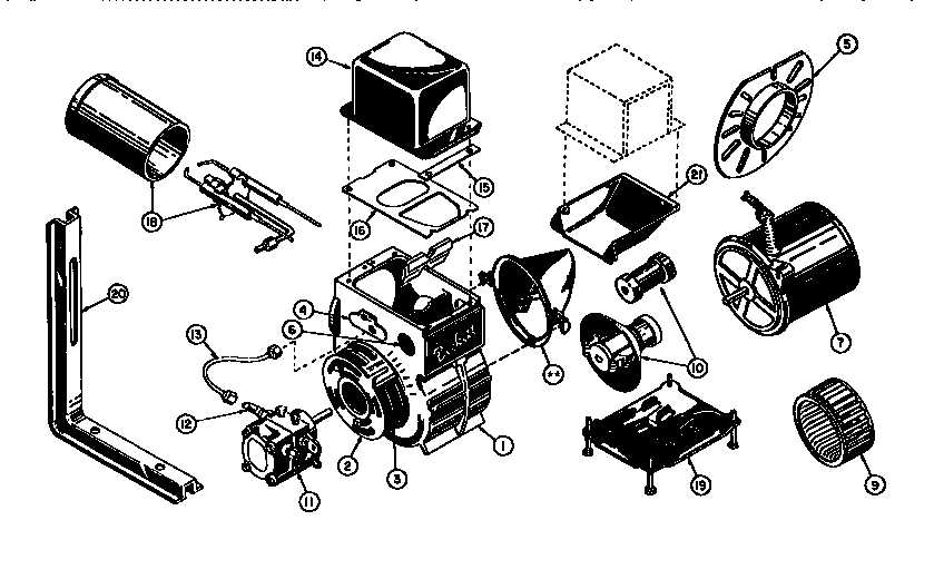
How to read the Beckett AFG oil burner parts diagram
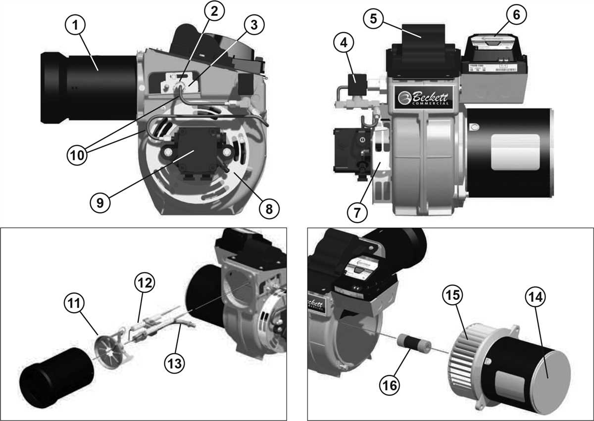
Understanding the Beckett AFG oil burner parts diagram is crucial for proper maintenance and troubleshooting of the oil burner. This diagram provides a detailed representation of the different components and their placement within the burner, allowing technicians and homeowners to identify and replace parts as needed. By familiarizing yourself with the diagram, you can effectively navigate the various components of the oil burner and ensure its optimal performance.
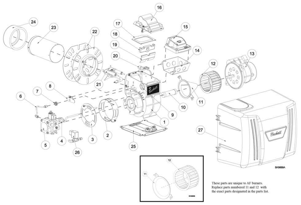
The Beckett AFG oil burner parts diagram typically consists of labeled illustrations, indicating the specific parts and their corresponding numbers. These numbers are used to identify each component when referring to the manufacturer’s literature or when ordering replacement parts. To read the diagram, start by identifying the major sections, such as the fuel pump, air tube assembly, and motor. Each major section will have sub-sections that further break down the components.
- Fuel pump: The fuel pump is a key part of the oil burner and is usually represented in the diagram as a labeled box or cylinder. It is responsible for drawing fuel from the tank and delivering it to the nozzle for combustion.
- Air tube assembly: This section includes components such as the air tube, blast tube, and nozzle. These parts work together to ensure the proper mixture of air and fuel for combustion. They are typically depicted as cylindrical or tubular shapes with labels indicating their specific names.
- Ignition system: The ignition system consists of electrodes and a transformer. These components generate a spark to ignite the fuel-air mixture in the combustion chamber. They are often shown as small geometric shapes or symbols.
- Motor: The motor is responsible for powering the various moving parts of the oil burner. It is usually depicted as a labeled rectangle or circle, indicating its location within the burner assembly.
When reading the Beckett AFG oil burner parts diagram, it is important to pay attention to the labels and numbers associated with each component. This information can help you identify and troubleshoot issues with the burner, as well as order the correct replacement parts. By understanding the diagram, you can effectively maintain and repair your Beckett AFG oil burner, ensuring its reliable operation and efficiency.
Troubleshooting common issues with the Beckett AFG oil burner
Operating an oil burner requires periodic maintenance and troubleshooting to ensure smooth and efficient operation. Here are some common issues that may occur with the Beckett AFG oil burner and how to troubleshoot them.
1. No ignition or flame loss
If the burner fails to ignite or the flame goes out during operation, there are several potential causes:
- Check if there is sufficient fuel in the tank, and if the oil filter is clean and not clogged.
- Inspect the electrodes and make sure they are clean and properly positioned.
- Ensure that the transformer is working correctly and providing enough voltage to the electrodes.
- If everything else checks out, the nozzle may be clogged and need replacement.
2. Poor combustion and excessive smoke
If you notice poor combustion or excessive smoke coming from the oil burner, consider the following:
- Check the air-to-fuel ratio adjustment. If it is too high or too low, it can cause incomplete combustion and excessive smoke. Adjust the air shutter or air band as necessary.
- Inspect the combustion chamber for any debris or soot buildup that may be obstructing proper airflow.
- Ensure that the draft regulator is properly adjusted and allowing for adequate draft in the combustion chamber.
- If the nozzle is worn or dirty, it may need to be cleaned or replaced for proper fuel atomization.
3. Excessive cycling or frequent shutdowns
If the burner is cycling on and off too frequently or experiencing frequent shutdowns, consider the following troubleshooting steps:
- Check the thermostat or burner controls for any faulty wiring or incorrect settings.
- Inspect the flame sensor or cad cell to ensure it is clean and functioning properly. Replace it if necessary.
- Verify that the oil pump is providing consistent and adequate oil pressure.
- Make sure that the igniter is not faulty and is providing a consistent spark for ignition.
In conclusion, troubleshooting the Beckett AFG oil burner involves checking various components such as fuel supply, electrodes, nozzle, combustion chamber, air/fuel ratio, draft regulator, thermostat, flame sensor, pump pressure, and igniter. By identifying and addressing these common issues, you can ensure optimal performance and reliable operation of your oil burner.