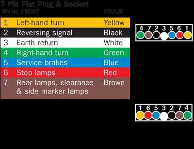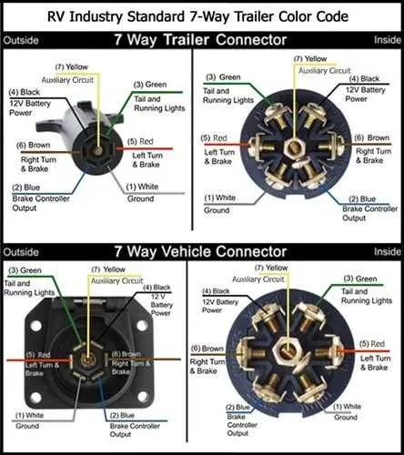
For reliable electrical connections, always ensure that each terminal is clearly labeled according to its function. This helps in quickly identifying the correct placement of wires in various devices. Properly mapping out the connections can prevent issues such as short circuits or faulty signals.
In systems with multiple contact points, follow a specific color-coding or numbering system to maintain consistency. This reduces the risk of confusion during installation or maintenance. Pay attention to the layout, ensuring that each pin corresponds to the correct circuit, and check that the voltage ratings match the components’ specifications.
Test each connection after installation to verify that the correct signals are being transmitted through the right channels. Use a multimeter to check for continuity and make sure all contacts are securely fitted. For robust setups, consider using locking mechanisms or cable ties to avoid accidental disconnections.
For advanced applications, such as automation systems, ensure that the interface between devices is capable of handling the expected load. Regularly inspect the connectors for wear and tear, particularly in environments with high humidity or frequent vibrations. When necessary, upgrade the hardware to accommodate higher current or more complex configurations.
Understanding a 7-pin Wiring Layout
For safe and efficient electrical connections in trailers, RVs, and similar applications, follow these key points when wiring a 7-pin setup:
- Pin 1: Ground – This pin is for the common ground. Always connect it to the chassis ground of your vehicle to ensure proper functioning of other circuits.
- Pin 2: Tail Light – Used for the tail light circuit. This should be wired to your vehicle’s tail light to illuminate the rear lights of the trailer.
- Pin 3: Left Turn Signal – This pin connects to the left turn signal. Ensure this wire is properly connected to the vehicle’s left blinker circuit for correct operation.
- Pin 4: Right Turn Signal – The right turn signal wire. This pin powers the right turn indicator of the trailer.
- Pin 5: Electric Brakes – This pin is responsible for activating the trailer’s brake system. It connects to your vehicle’s brake controller, providing proportional braking power to the trailer.
- Pin 6: Reverse Lights – Used to power reverse lights on the trailer. This is connected to the vehicle’s reverse light circuit, enabling the lights to activate when reversing.
- Pin 7: 12V Power Supply – This pin delivers 12V from the vehicle to charge the trailer’s battery. Ensure proper gauge wiring to handle the power load.
Correctly wiring each pin ensures that all functions, such as lighting and braking, operate as intended and comply with safety standards. Always verify the wiring against your vehicle’s manual and use high-quality, corrosion-resistant connectors to guarantee a durable connection.
Understanding the Pinout of a 7-Pin Plug

To properly wire a 7-pin plug, it’s crucial to identify each pin’s function. The first pin is typically reserved for the ground connection, ensuring a stable electrical path. Pin 2 is often used for the tail light circuit, providing power to the rear lighting system. Pin 3 is dedicated to the left turn signal, while pin 4 handles the right turn signal. Pin 5 generally serves as the brake light connection, activated when the brakes are applied.
Pin 6 is designated for the reverse light circuit, which is activated when the vehicle is shifted into reverse. Finally, pin 7 is used for auxiliary power, allowing additional power supply for accessories such as electric brakes or additional lights.
When wiring, double-check each pin’s placement on the plug to avoid misconnection, which could lead to malfunction or damage to the electrical system. It’s also advised to use the correct gauge of wire for each circuit to ensure proper current flow without overloading the system.
How to Wire a 7 Pin Plug for Trailer Hookups
Start by identifying the pins on the plug: typically, there are 7 positions, each serving a specific purpose. Use a multimeter to test the correct voltage output from the vehicle’s electrical system to ensure compatibility.
Begin with the ground wire, usually connected to the metal casing of the plug. This is essential to complete the circuit. Securely attach the ground wire to the appropriate pin and make sure it’s firmly tightened to avoid any connection issues.
The next pin is for the tail light circuit. This wire should run from the vehicle’s tail light system to provide the necessary power for the trailer’s rear lights. Double-check the color codes to avoid mistakes: usually, it’s a brown wire.
For turn signals, connect the left and right turn signal wires. Typically, the left turn signal uses a yellow wire, and the right turn signal uses a green one. Test each wire by activating the respective turn signal in the vehicle.
The brake light signal uses a separate wire, often marked with red. This wire must be connected to the vehicle’s brake light system to ensure proper braking functionality on the trailer.
Power for the trailer’s electric brakes is often supplied through a dedicated pin. This wire is typically blue, and it should be connected directly to the trailer’s braking system, ensuring the correct polarity and securing a reliable connection.
Next, connect the reverse lights. This wire is commonly white or purple. Ensure that this wire is connected to the vehicle’s reverse light circuit, so the trailer’s reverse lights are activated when the vehicle is in reverse.
Finally, connect the auxiliary 12V power supply wire, if your trailer requires additional power, such as for a breakaway system or battery charging. This wire is often black and should be connected to a power source that remains live even when the ignition is off.
Once all wires are securely attached to their respective pins, double-check each connection. After that, test the trailer hookup by activating each function (tail lights, brake lights, turn signals, etc.) to ensure everything works correctly. Tighten any loose connections and ensure no exposed wires are present.
Troubleshooting Common Issues with 7 Pin Plugs

Check the wiring for proper connection order. Miswiring is the most common issue, often resulting in malfunctioning signals. Cross-referencing the color code of the cables with the manufacturer’s manual is crucial to ensure proper placement.
If there is no power or lights, inspect the fuse. A blown fuse is often the result of a short circuit or overload. Replacing the fuse is an easy fix, but identifying the root cause (such as a worn-out wire) is important to prevent recurring problems.
For intermittent signal loss, examine the pins for corrosion or dirt buildup. Cleaning the pins and ensuring a tight fit can resolve this issue. Using dielectric grease on the pins can also help maintain a reliable connection and prevent moisture-related problems.
If the electrical system is grounded incorrectly, it can cause erratic behavior in connected devices. Ensure the grounding pin is correctly wired and securely fastened to the vehicle’s chassis. A loose or missing ground connection often leads to malfunctioning of trailer lights or brakes.
In case of signal mismatch, check for compatibility between the towing vehicle and the trailer system. Some older trailers may have different wiring standards that don’t align with newer systems. Adapting the wiring may be necessary for proper signal transmission.
Faulty connections due to worn-out or damaged cables should be replaced. Pay attention to areas where cables might rub against the vehicle or trailer frame, as these spots are prone to insulation wear, leading to shorts or broken circuits.