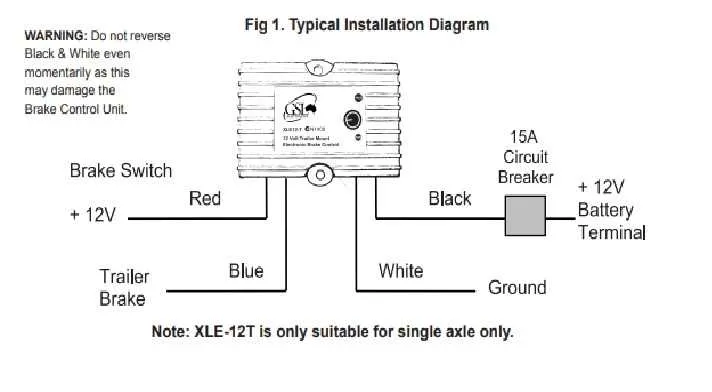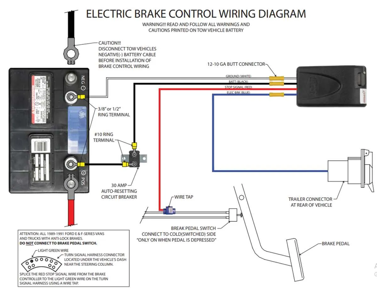
To ensure proper functionality, focus on connecting the electrical system of your towing setup. Start by establishing a secure link between the power supply and the mechanism that activates the braking system on the attached load. This will allow you to control the force applied based on your driving needs.
First, ensure that the power cable is adequately fused to prevent overloads. The ground connection should be firmly secured to avoid any interruptions in the electrical flow. It is crucial to use the correct gauge wire to avoid overheating and ensure safe operation over time.
Next, connect the control unit, which adjusts the intensity of the applied force, to the primary circuit. This device usually requires a signal from the vehicle’s braking system to synchronize its actions with the vehicle’s movements. Double-check that the signal wire is routed in a way that prevents interference with other systems.
Lastly, pay attention to the connectors and make sure they are rated for the specific electrical load. Using high-quality connectors minimizes the risk of corrosion and ensures longevity. Always verify the complete setup before use to ensure everything functions smoothly under varying conditions.
Electrical Setup for Towing Safety Systems

Ensure that the power supply is connected to the towing vehicle’s brake signal output. The first step is to link the power source to the primary relay, which directs electricity to the braking mechanism of the attached load. Verify that the positive wire from the towing vehicle’s electrical system is correctly routed to the input terminal of the activation module.
Next, connect the ground wire from the mechanism to the towing vehicle’s chassis or designated grounding point. This connection ensures proper functioning by preventing electrical faults during operation. The wiring should be insulated to prevent short circuits from any exposed wiring.
Secure a lead from the vehicle’s signal input terminal to the activation system, ensuring that the cable is adequately sized to handle the electrical load. The output from the activation unit must be connected to the load, with attention given to any required adjustments based on the braking force needed for different towing loads.
Lastly, check for compatibility with the vehicle’s electrical setup. For vehicles with a dedicated towing package, use the pre-existing connections for simplified installation. Regularly test the setup to confirm reliable performance, adjusting the power flow where necessary based on feedback from the system’s indicators.
Understanding the Pinout and Layout for Electric Tow System Components
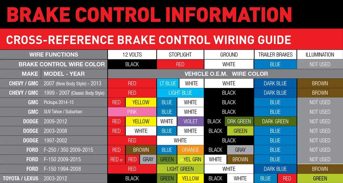
Start by identifying the power input pin, typically connected to the vehicle’s battery or a dedicated power supply. This pin ensures the system has a constant voltage source, usually 12V DC. The ground connection, commonly labeled as GND or negative, must be securely attached to the vehicle chassis to ensure proper electrical flow.
The signal pin is crucial for transmitting control commands. It should be linked to the vehicle’s electric signal output, which dictates the activation level. For a smooth operation, ensure the connector matches the vehicle’s designated output port to avoid signal inconsistencies.
Next, the safety pin acts as a failsafe, often connected to the vehicle’s brake light circuit. When activated, it allows the system to operate only when the vehicle’s brake lights are engaged, ensuring no power is delivered to the towing setup when not needed.
In some systems, an auxiliary pin is available to manage additional functions like LED indicators or a feedback mechanism. This pin, if present, should be connected to an auxiliary circuit within the vehicle’s electrical system for full functionality.
Finally, confirm the orientation of all connections. Improper placement of the signal or safety pins could cause erratic behavior, while reversed power and ground wires may result in short circuits. Always consult the vehicle’s manual for specific connection details.
Step-by-Step Guide to Connecting a Trailer Brake Controller to Your Vehicle

Start by ensuring your vehicle is equipped with the necessary connector for towing. The most common connection type is a 7-pin connector located near the rear bumper. If your vehicle doesn’t have one, you may need to install a towing harness before proceeding.
Next, locate the correct pins on your vehicle’s connector. For most setups, the pin that carries power to the braking system is usually labeled and located near the center. You will connect this to the corresponding terminal on the unit in your towing setup.
Secure a reliable ground connection. This typically involves attaching a wire from the unit to a clean, unpainted metal surface on your vehicle’s frame. This is crucial to ensure proper functioning of the entire system.
Now, connect the power wire. Using an appropriate gauge wire, link the power source from the vehicle to the power terminal on the braking system. Make sure the wire is routed away from hot surfaces or moving parts that could cause wear and tear.
Set up the activation switch inside your vehicle. This is often mounted in a convenient location within the driver’s reach, ensuring it can be easily operated while driving. It will control the engagement of the towing mechanism as needed.
After completing the connections, test the setup. It’s vital to verify that the system activates correctly when the vehicle slows down. Make any necessary adjustments to ensure smooth operation.
Finally, secure all wires with proper insulation and fasteners. Check for any loose or exposed wires that could lead to electrical shorts or damage. Once everything is tightly fastened and insulated, you’re ready for towing.
Troubleshooting Common Issues with Wiring Connections for Trailer Systems
If the system is not functioning as expected, begin by checking the power source. Ensure that the fuse is intact and there are no loose connections at the power input. A blown fuse can prevent the entire setup from operating properly.
Next, inspect the ground connection. A poor ground can cause intermittent performance or total failure of the setup. Clean any corrosion from the ground terminal and ensure it is tightly secured to the vehicle chassis.
- Verify that the connection at the vehicle end is free of rust or dirt.
- Check for any exposed or frayed cables that may cause short circuits.
It is important to ensure that the pin connections are accurate. Miswiring is a common problem and may cause specific components to fail. Cross-referencing the system’s manual can help confirm that each pin is assigned correctly.
- Check for continuity in each wire to ensure signals are being transmitted without interruption.
- Test the system’s functionality at different power levels to confirm correct operation.
If the system is still unresponsive, perform a voltage test along the entire line. Any significant voltage drop indicates that the circuit might be experiencing resistance. Use a multimeter to locate areas of poor contact or damage.
- Ensure the voltage matches the specifications for each component involved.
- Inspect the connectors for signs of overheating or melting.
Lastly, inspect any control modules or relays that manage the system. These can become damaged due to electrical spikes. Testing the components individually and replacing faulty parts is necessary to restore proper function.