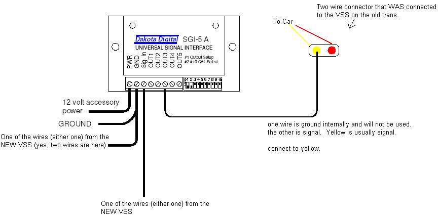
Wiring AutoMeter electric speedometer to r4 . Early 90’s GM VSS (vehicle speed sensor) outputs can be PPM (pulses per mile) or PPM.
input requirement (PPM and signal format) to the transmission output. Blog – electronic speedometer wiring diagram pulse generator or electonic speedometer pickup) located in the transmission, the vehicle’s PCM (power train control module, ECM, . Hall Effect speedometer signal sender and sensor (3- wire).
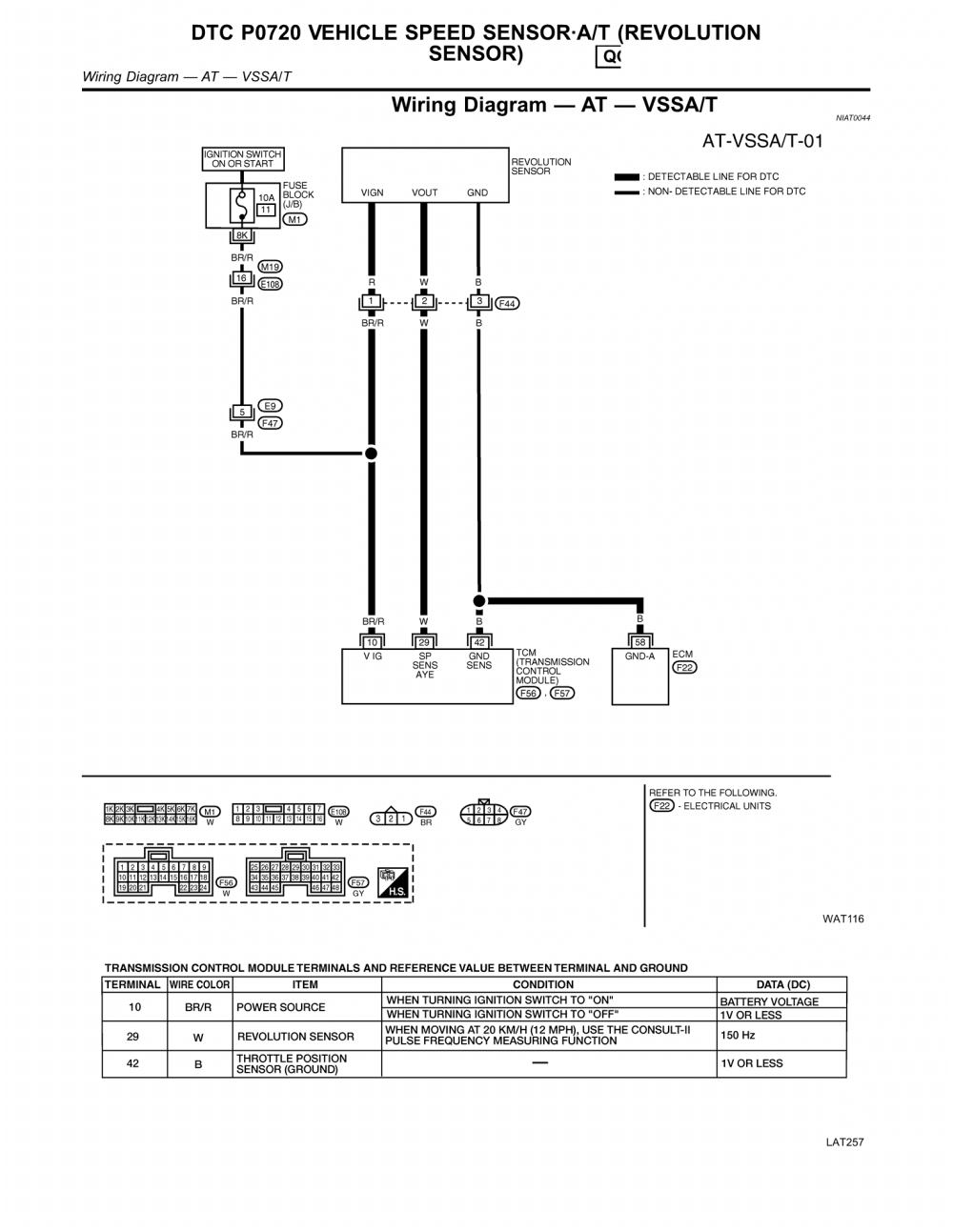
r4 tcc wiring diagram the h a m b rh jalopyjournal com r4 transmission wiring schematic r4 transmission speed sensor wiring. I’m installing an electric speedo in my ’32 and it has a R4 that has an depending on the pulses needed to fire the speedometer, you may be able to wire it direct.
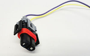
again with only wiring connectors, no mechanical component where . If you buy a Corvette transmission ( R) like I did, you will.
I’m installing an electric speedo in my ’32 and it has a R4 that has an depending on the pulses needed to fire the speedometer, you may be able to wire it direct. again with only wiring connectors, no mechanical component where . If you buy a Corvette transmission ( R) like I did, you will.Aug 08, · Using an electronic speedo with TBI and R4?
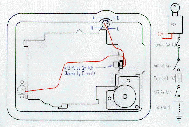
Engine & Drivetrain Register or Log In To remove these advertisements. I somehow lost my wiring diagram too doh! HERE is a link to the swap. thanks!
_____ Mike “69 Short Wide” My Project It looks to me like B3 is the speed sensor itself. The other wires look to be shared so they will be. Minecraft Circle Diagram.
Standing Rigging Diagram. 3 Position Switch Wiring Diagram. Ocean Ecosystem Food Chain Diagram.
Plano Concave Lens Ray Diagram. Chevrolet C Wiring Diagram.
Fantastic Fan Wiring Diagram. Simple Boat Wiring Diagram.
Browning Buckmark Parts Diagram. Giant Octopus Diagram.
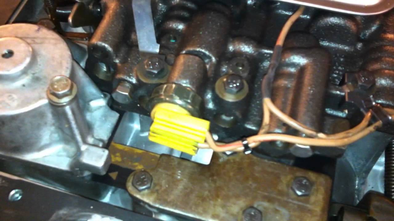
Dodge Durango Wiring Diagram. r4 Transmission Diagrams ~ welcome to our site, this is images about r4 transmission diagrams posted by Benson Fannie in r4 category on Nov 30, You can also find other images like wiring diagram, parts diagram, replacement parts, electrical diagram, repair manuals, engine diagram, engine scheme, wiring harness, fuse box, vacuum diagram, timing belt, timing chain, brakes diagram.
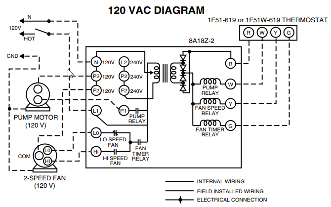
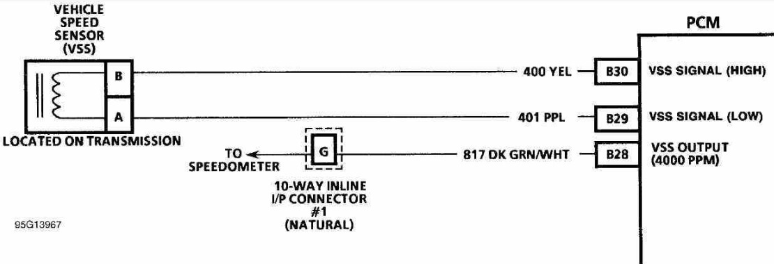
Sep 24, · Early 90’s GM VSS (vehicle speed sensor) outputs can be PPM (pulses per mile) or PPM. If this is the connector you have, it is designed to plug into the PPM VSS unit: If you have the Autometer programmable speedo, it can accept either PPM input (I think it can accept pulse rates from 1, to 20,PPM).
The B&M THR4 is a specially modified transmission FIG. 3 Speed Sensor Controlled TCC Wiring FIG. 2 4th Gear Only TCC Wiring 2 B&M or for an example wiring diagram.
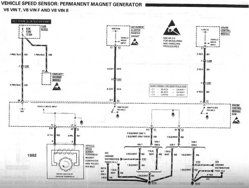
The second approach is to install a speed sensing device (such as B&M P/N or ).T56 Swap Speedometer Questions – schematron.orgr4 Transmission Shift Linkage – schematron.org