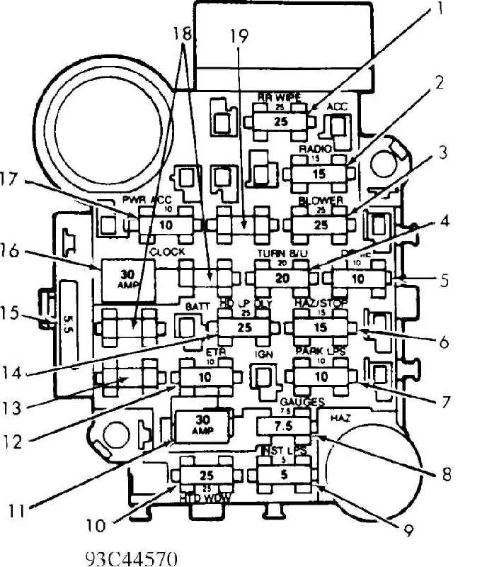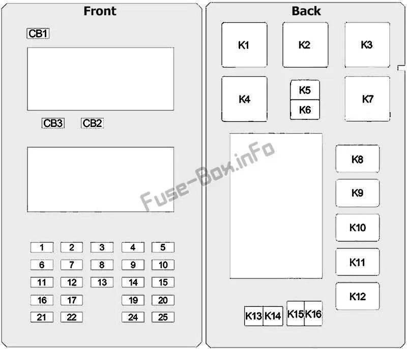
To avoid electrical malfunctions in your 1998 model, start by familiarizing yourself with the component layout that controls the vehicle’s power distribution. A clear understanding of the connections and the location of various relays and circuits will save you time during troubleshooting.
Refer to the illustration for accurate placement of essential elements, including power connections, current regulators, and ground systems. These critical elements ensure your vehicle’s electrical network operates smoothly, minimizing the risk of shorts or disruptions.
Locate the main panel under the dashboard or in the engine compartment, depending on the specific setup of your vehicle. Check the labels carefully, as each port is dedicated to a different function, from interior lighting to engine management systems. Proper identification of these ports will prevent accidental disconnections and ensure you are working with the correct components when performing maintenance.
Make sure to keep a toolset on hand to disconnect or replace any damaged parts. Following the correct order when manipulating these components will avoid unnecessary strain on the system, and proper reassembly is critical for maintaining vehicle performance.
98 Vehicle Electrical Layout

To ensure proper operation of your car’s electrical system, refer to the following guide for the placement of key components. The primary unit for handling electrical connections is located near the driver’s side dashboard. Check the area under the hood for another essential unit, typically situated close to the battery.
Start with the front section, where you’ll find relays responsible for ignition and engine management. These are often in the first few positions of the interior unit. For the rear lighting and power windows, look towards the midsection, where the corresponding connections are made.
If you experience any issues with the headlights, they are often controlled by relays found near the front of the unit. For problems with climate control or air conditioning, focus on the rear-most relays in the interior layout.
For power distribution, examine the large connection points. These provide power to critical systems like airbags, anti-lock brakes, and transmission controls. Ensure these high-capacity connectors are intact and not corroded.
Always confirm the correct amperage when replacing any damaged parts. Using the wrong amperage can lead to electrical failure or damage to sensitive components.
For troubleshooting, consult the specific layout for each section of the vehicle’s internal electrical network, ensuring all circuits are properly labeled for easy identification.
Locating and Identifying the Electrical Component Panel in a 1998 SUV
The primary electrical panel is located under the dashboard on the driver’s side. Look beneath the steering wheel, near the footwell, to find a small cover. Remove this panel to expose the internal circuitry connections.
A secondary unit can be found in the engine compartment, near the battery. This unit is typically situated on the passenger side, close to the firewall. Ensure the vehicle is powered off before accessing this area to avoid electrical shock.
Both components are labeled for easy identification. Use the manufacturer’s manual to cross-reference the labels with the corresponding systems they control.
In case of difficulty, check for a small diagram on the rear of the panels, which usually provides a quick guide to the exact location of critical elements and their functions.
Understanding the Layout and Function of Each Component
Start by locating the electrical distribution panel and identifying each circuit it powers. Properly labeled positions and values are essential for diagnosing issues and performing repairs. Here’s how to approach the layout:
- Main Circuits: Typically located in the center or primary section. These power critical systems such as ignition, headlights, and airbags. Always check the amperage rating to avoid overloading.
- Interior Systems: Often placed on the side or in a separate smaller area. These components control dashboard electronics, interior lights, and HVAC systems. They usually have lower amperage ratings.
- Accessories: Usually positioned near the perimeter or in the secondary panel. They handle the power for radios, power windows, and auxiliary ports. These should be checked regularly to ensure proper operation.
For every individual circuit, refer to the amperage values and their specific roles:
- High-Amperage Circuits: Handle larger systems like the engine control unit and transmission. Make sure the protection components for these systems are intact to avoid damage to sensitive parts.
- Low-Amperage Circuits: These are used for lighting, sensors, and communication modules. These circuits often require precise and accurate troubleshooting.
- Spare Fuses: Always ensure there are replacements readily available for emergency fixes. They should match the exact specifications of the original component to avoid electrical malfunctions.
Familiarizing yourself with the layout and ensuring that each circuit is correctly matched with the appropriate amperage will help in maintaining the overall integrity of the electrical systems.
Troubleshooting and Replacing Electrical Components in a 98 Vehicle System

If you experience electrical issues, check the power distribution panel first. It’s crucial to inspect the connectors and individual units that regulate various vehicle functions like lighting, HVAC, or engine sensors. Start by visually scanning for any burnt or damaged elements.
To replace a faulty component, use a pair of needle-nose pliers to gently remove the malfunctioning unit from its slot. Be sure to match the new part to the correct amperage rating. Avoid inserting a higher-rated part as it could cause wiring damage or other system failures.
In case of frequent electrical malfunctions, inspect all connecting wires for wear and tear. Sometimes, a poor connection or corrosion can disrupt the current flow. Clean any rust from terminals with an electrical contact cleaner and ensure that each terminal is securely fastened to prevent loose connections.
If you’re uncertain about which unit is malfunctioning, a multimeter can be an effective tool to check the continuity of each part. Set the multimeter to test for electrical flow and check the contact points. A lack of continuity suggests the part needs replacing.
Finally, always keep a set of spare parts on hand for quick replacements. This will save time and reduce the risk of further damage to your vehicle’s electrical system in the future.