
When it comes to heating and cooling systems, zone valves play a crucial role in controlling the flow of hot and cold water or air to different areas of a building. One popular brand of zone valves is Taco, known for their durability and reliability. In this article, we will discuss how to properly wire multiple Taco zone valves to ensure efficient and effective operation of your heating or cooling system.
Before diving into the wiring process, it’s important to understand how zone valves work. Zone valves are typically installed in the piping system of a heating or cooling system and are controlled by a thermostat. When the thermostat signals a need for heating or cooling in a particular zone, the zone valve opens, allowing the flow of hot or cold water or air to that zone. This helps regulate the temperature in different areas of a building, providing comfort and energy savings.
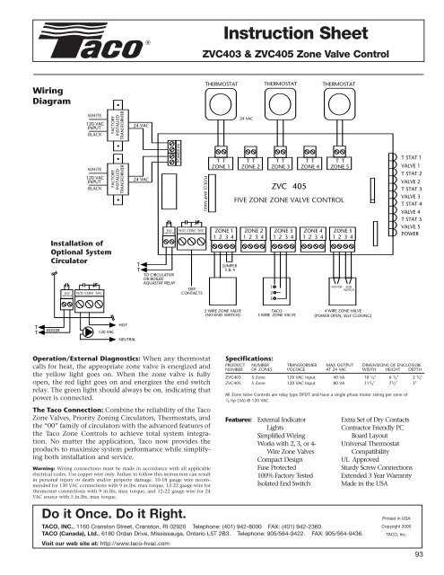
Wiring multiple Taco zone valves requires attention to detail and following the manufacturer’s instructions. Each Taco zone valve comes with its own wiring diagram, which should be carefully read and understood before proceeding with the installation. It is important to note that the wiring process may vary depending on the specific model of Taco zone valve you are using.
Understanding Taco Zone Valves and Their Wiring
When it comes to controlling the flow of hot water in a hydronic heating system, Taco zone valves are an essential component. These valves are designed to open and close, allowing or blocking the flow of water to different zones or areas in a building. Wiring multiple Taco zone valves correctly is crucial to ensure proper functioning and efficient heating distribution throughout the different zones.
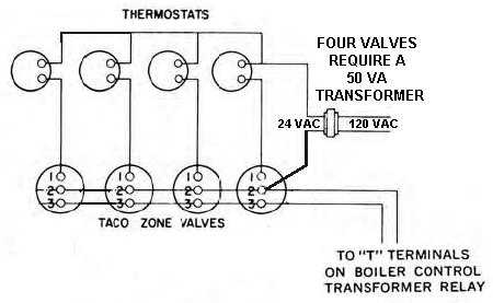
The wiring of Taco zone valves may vary depending on the specific model and the setup of the heating system. However, there are some general principles to keep in mind. Each Taco zone valve typically has two wires, a red wire (usually connected to the thermostat) and a white wire (connected to the transformer). The red wire carries the signal from the thermostat to open or close the valve, while the white wire provides power to the valve from the transformer.
It is important to understand the concept of “end switches” in Taco zone valves. These end switches are additional terminals on the valve that can be used to control other components of the heating system, such as the boiler or circulator pump. By wiring these end switches appropriately, you can enable the system to start or stop when a zone valve opens or closes.
- When wiring multiple Taco zone valves, it is crucial to have a clear understanding of the zoning layout and requirements of the heating system. This includes knowing the number of zones, their respective thermostat locations, and the desired sequence of operation.
- Properly labeling the wires and valves can help simplify the installation and troubleshooting process. Each zone valve and its corresponding wires should be clearly identified to avoid confusion.
- Using a wiring diagram or consulting the manufacturer’s instructions is highly recommended. Different models of Taco zone valves may have specific wiring configurations, and following the provided guidelines can ensure a successful installation.
- Testing the wiring and functionality of each zone valve is essential before putting the heating system into operation. This includes checking for proper opening and closing of the valves, as well as verifying the connection with the thermostat and other components.
By understanding Taco zone valves and their wiring requirements, you can ensure an efficient and reliable hydronic heating system. Proper installation and wiring can enhance the comfort and energy efficiency of the building, providing warmth and comfort throughout the different zones.
Zone Valve Basics
Zone valves are essential components in a hydronic heating system that help control the flow of water to different zones or areas in a building. They act as mechanical valves that open and close based on the temperature needs of individual areas, allowing for customized comfort and energy efficiency.
Each zone valve consists of a valve body, actuator, and end switch. The valve body is responsible for controlling the flow of water, while the actuator is an electric motor that opens and closes the valve. The end switch is a feature that can be used to activate other devices, such as a circulator pump, when the valve is fully open.
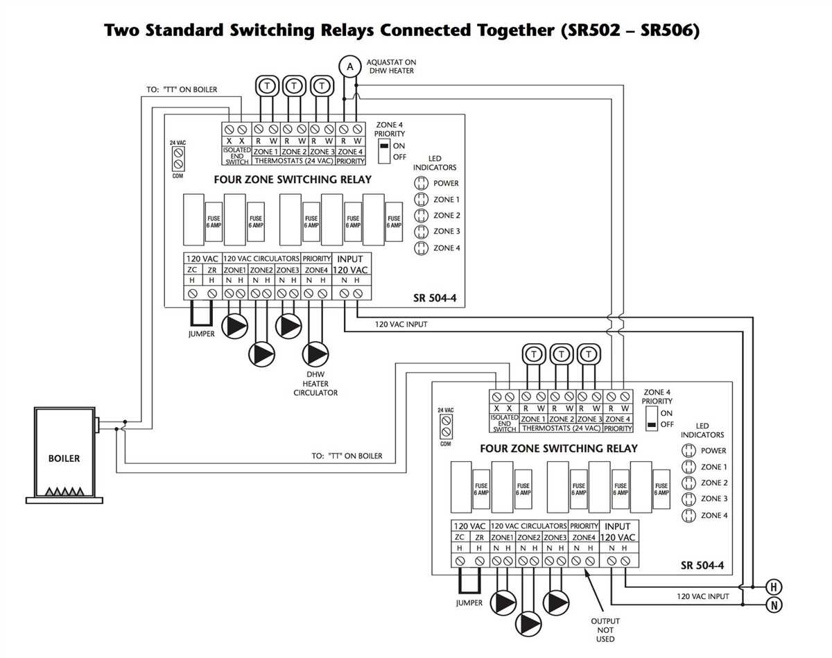
When multiple zone valves are used in a system, they are typically wired together to a control panel or relay. The wiring configuration may vary depending on the specific system and controls being used, but there are some general principles to keep in mind. Each zone valve will require a power supply, typically 24 volts, and a common connection to complete the circuit. The control panel or relay will also connect to the thermostat for each zone, allowing for individual temperature control.
It is important to follow the manufacturer’s instructions and wiring diagrams when installing and wiring multiple taco zone valves. Proper installation and wiring ensure the correct operation of the system and prevent any potential damage or malfunctions. Consulting a professional HVAC technician is recommended for complex installations or if you are unsure about the wiring process.
Determining the Number of Zone Valves Needed
When it comes to wiring multiple Taco zone valves for a heating system, one of the key factors to consider is the number of zone valves needed. The number of zone valves you’ll require will depend on the specific layout and needs of your heating system.
To determine the number of zone valves needed, you’ll need to assess the number of separate heating zones in your system. A zone is an area of your home that requires independent temperature control, such as different rooms or floors. Each zone will require its own zone valve to regulate the flow of hot water or steam.
Start by identifying the different heating zones in your home. For example, if you have a two-story house with a separate heating system for each floor, you’ll likely need two zone valves. If you have additional heating zones, such as one for your basement or a separate zone for an addition to your home, you’ll need to account for those as well.
Once you have determined the number of heating zones, you can plan the wiring and installation of the zone valves. It’s important to ensure that each zone valve is wired properly to the control panel and that they are all interconnected to provide efficient and effective heating control throughout your home.
In summary, determining the number of zone valves needed for your heating system requires assessing the number of independent heating zones in your home. Each heating zone will require its own zone valve for temperature control. By accurately identifying the zones in your home, you can ensure that your wiring and installation of multiple Taco zone valves is done correctly for optimal heating efficiency.
Wiring Zone Valves to the Control Panel
Wiring zone valves to the control panel is an essential step in setting up a zoned heating system. Zone valves are responsible for controlling the flow of hot water or steam to different areas or zones in a building, allowing for personalized temperature control in each zone. In order to properly wire zone valves to the control panel, it is important to follow the manufacturer’s instructions and adhere to industry standards.
Step 1: Understand the Wiring Diagram
Before beginning the wiring process, it is crucial to thoroughly review the wiring diagram provided by the manufacturer. The wiring diagram will indicate the specific connections and terminals that need to be made between the zone valves and the control panel. It is important to understand the different components and their functions before proceeding with the wiring process.
Step 2: Gather the Necessary Tools
Next, gather all the necessary tools and materials needed for the wiring process. This may include wire strippers, electrical tape, wire nuts, a screwdriver, and a multimeter for testing electrical connections. Ensure that you have the correct gauge and type of wire specified in the manufacturer’s instructions.
Step 3: Make the Electrical Connections
Following the wiring diagram, carefully connect the wires from the zone valves to the corresponding terminals on the control panel. Each zone valve will typically have two wires: one for power (usually labeled “R” or “W”) and one for control (typically labeled “C” or “T”). Use wire nuts to securely connect the wires, ensuring there are no loose or exposed wires.
Step 4: Test the Connections
Once all the electrical connections have been made, it is important to test the system to ensure proper functionality. Use a multimeter to test the voltage at the control panel terminals to ensure that power is being properly supplied to the zone valves. Additionally, test the control wires to verify that they are properly functioning and communicating with the control panel.
Following these steps and referring to the manufacturer’s instructions will help ensure a successful wiring of zone valves to the control panel. It is important to exercise caution while working with electrical connections and to consult a professional if needed. Proper wiring is essential for the optimal performance of a zoned heating system and can contribute to energy efficiency and comfort in a building.
Wiring Zone Valves in Parallel
The wiring of zone valves in parallel is a common practice in HVAC systems that have multiple zones. This configuration allows for the independent control of each zone by providing a dedicated power and control signal to each zone valve. Wiring zone valves in parallel offers several advantages, including increased flexibility and reliability.
In parallel wiring, each zone valve is connected to the same power source and control signal. This means that all zone valves receive the same voltage and control commands simultaneously. It simplifies the wiring process as only one power source and control panel are needed for all zones. Additionally, parallel wiring allows for easy troubleshooting and maintenance, as each zone valve can be tested and serviced independently.
When wiring zone valves in parallel, it is important to ensure that the power source and control panel can handle the combined electrical load of all the zone valves. The wiring should be done using appropriate gauge wires to prevent voltage drops and overheating. It is also critical to properly label and document the wiring connections to avoid confusion in the future.
Overall, wiring zone valves in parallel offers an efficient and effective way to control multiple zones in an HVAC system. It provides the ability to individually regulate the temperature and airflow in each zone, improving comfort and energy efficiency. Whether in residential or commercial settings, parallel wiring of zone valves is a reliable solution for managing HVAC systems with multiple zones.
Wiring Zone Valves in Series
When wiring multiple taco zone valves in a heating system, it is important to understand the concept of wiring them in series. Wiring zone valves in series means that the electrical connection between the valves is made in a sequential manner, with the electrical current passing through each valve in order.
To wire zone valves in series, the first valve is connected to the power source and the thermostat, while the subsequent valves are connected to each other in a daisy-chain fashion. This means that the wires connecting the second valve to the first valve should be connected in parallel to the wires connecting the first valve to the power source and thermostat.
When wiring zone valves in series, it is important to ensure that the total current passing through the series circuit does not exceed the maximum current rating of the valves or the power source. This can be achieved by properly sizing the electrical conductors and using appropriate circuit breakers or fuses.
Key considerations when wiring zone valves in series:
- Ensure proper wire gauges are used to handle the current load
- Make secure electrical connections to prevent loose or faulty connections
- Verify the compatibility of the power source and the valves
- Follow the manufacturer’s wiring instructions and diagrams
- Test the system after wiring to ensure proper operation
Wiring zone valves in series is a common practice in hydronic heating systems and allows for better control and zoning of different areas in a building. By understanding the principles of series wiring and following the necessary precautions, installers can ensure the proper and efficient operation of the zone valve system.
Troubleshooting Zone Valve Wiring Issues
In this final section, we will discuss some common troubleshooting steps for resolving zone valve wiring issues. It is important to remember that working with electrical systems can be dangerous, and it is recommended to consult a professional if you are unsure or uncomfortable with these procedures.
1. Check Power Supply
The first step in troubleshooting zone valve wiring issues is to check the power supply. Ensure that the system is receiving the correct voltage and that there are no circuit breaker trips or blown fuses. If there is no power, inspect the wiring connections and look for any loose, damaged, or disconnected wires.
2. Verify Thermostat Connections
Next, verify the thermostat connections. Make sure that the thermostat is properly wired to the zone valve control, and that the wiring matches the manufacturer’s instructions. Check the thermostat settings to ensure it is calling for heat or cooling in the desired zone.
3. Test Zone Valve Functionality
If the power supply and thermostat connections are correct, the next step is to test the zone valve functionality. Activate the zone valve manually or via the thermostat to see if it opens and closes properly. If the valve does not respond, it may be faulty and require replacement.
4. Inspect Zone Valve Motor

If the zone valve is not functioning properly, inspect the motor. Check for any signs of damage, such as burning or melting, and ensure that the motor is receiving power. If the motor is damaged or not receiving power, it may need to be replaced.
5. Evaluate Wiring Connections
If all else fails, carefully evaluate the wiring connections. Check for any loose, damaged, or incorrect connections. Ensure that the wires are properly connected to the correct terminals and that there are no frayed or exposed wires. Correct any wiring issues as necessary.
By following these troubleshooting steps, you can identify and resolve common zone valve wiring issues. If you are unable to fix the problem or are uncomfortable working with electrical systems, it is best to consult a professional technician to ensure safe and effective resolution.
Disclaimer: The information provided in this article is for informational purposes only and should not be considered as professional advice. Always consult a qualified technician or electrician for proper diagnosis and repair.