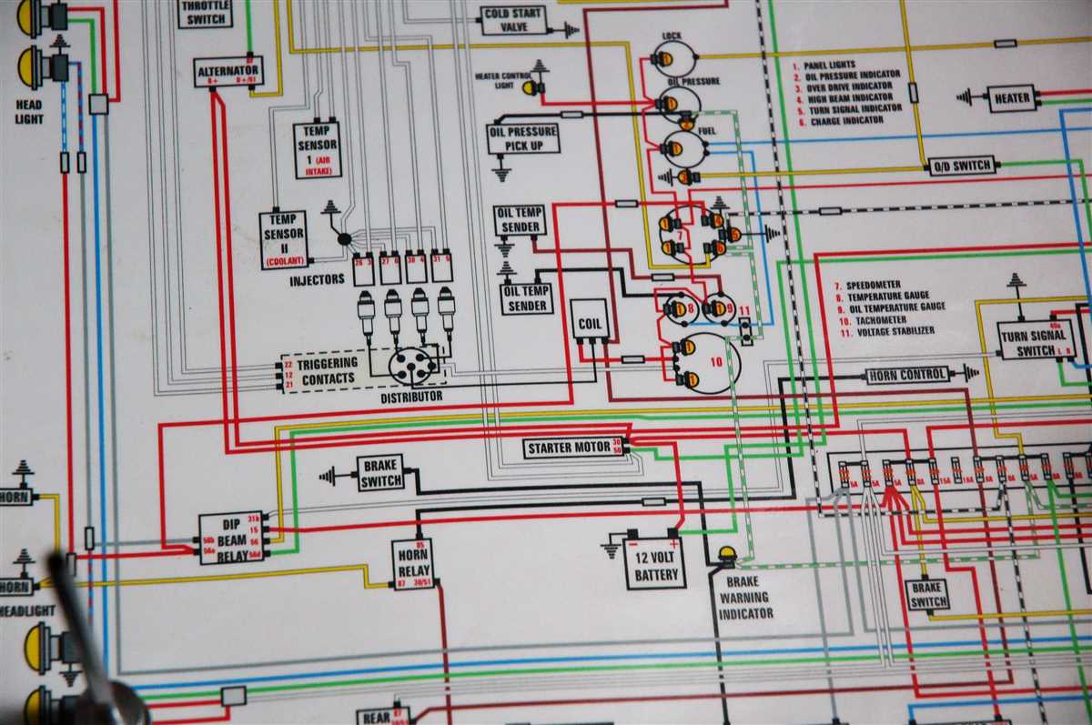
A universal wiper switch is a crucial component in any vehicle’s wiper system. It allows the driver to control the operation of the wiper blades and ensure clear visibility in various weather conditions. Whether you’re replacing a faulty switch or installing a new one, understanding the wiring diagram is essential to ensure proper installation and functionality.
The universal wiper switch wiring diagram provides a visual representation of how the different terminals and wires in the switch should be connected. This diagram outlines the connections for various functions, including the different wiper speeds, intermittent settings, and the wash function. It’s important to refer to this diagram to ensure that the switch is wired correctly and that the wipers function as intended.
When examining the universal wiper switch wiring diagram, there are often different terminals labeled with numbers or letters. These terminals correspond to specific wires that need to be connected to different components of the wiper system. It’s crucial to carefully follow the diagram and connect the wires accordingly to avoid any electrical issues or malfunctions.
What is a universal wiper switch wiring diagram?
A universal wiper switch wiring diagram is a schematic representation of the electrical connections and components required to properly install and operate a universal wiper switch in a vehicle. This diagram provides a visual guide for connecting the necessary wires and understanding the functionality of the switch.
The universal wiper switch is designed to be compatible with a variety of vehicle models and brands. It is typically used to control the operation of the windshield wiper system, including the speed settings and intermittent function. A proper wiring diagram is essential for correctly installing the switch and ensuring its proper functionality.
The wiring diagram will typically include information on the different terminals of the switch and how they should be connected to the vehicle’s electrical system. It will also indicate the appropriate wire colors and connections for different functions, such as park, low speed, high speed, and intermittent wiper settings.
Using a universal wiper switch wiring diagram can help to simplify the installation process and reduce the risk of incorrect connections or damaging the switch. It provides a clear understanding of how the switch should be wired and connected to the vehicle’s electrical system, ensuring proper operation of the windshield wiper system.
Understanding the basics of a universal wiper switch wiring diagram
A universal wiper switch wiring diagram is a schematic representation of the electrical connections involved in operating the wiper system of a vehicle. This diagram is crucial for understanding how the switch functions and how to properly install and connect it. By familiarizing yourself with the basics of a universal wiper switch wiring diagram, you can ensure that your wiper system operates correctly and efficiently.
At its core, a universal wiper switch wiring diagram consists of various symbols and lines that represent the different electrical components and connections. These include the switch itself, the wiper motor, the power source, and the various wires that connect them together. By studying the diagram, you can identify which wires should be connected to which terminals on the switch and motor, allowing for proper operation.
The universal wiper switch wiring diagram typically includes labeling for different switch positions and functions. For example, there may be positions for off, low-speed, high-speed, and intermittent settings. These labels indicate which terminals on the switch should be connected to achieve the desired wiper speed or functionality.
In addition to the switch positions, a universal wiper switch wiring diagram may also include information about additional components, such as relays or fuses, that are necessary for the proper functioning of the wiper system. These components help protect the electrical system from overloads and prevent damage to the switch and motor.
By understanding the basics of a universal wiper switch wiring diagram, you can confidently install and connect the switch in your vehicle. It is important to follow the wiring diagram closely to ensure that all connections are made correctly, as any incorrect wiring can result in malfunctioning wipers or even damage to the electrical system. If you are unsure about any aspect of the wiring process, it is advisable to seek professional assistance to ensure a safe and reliable installation.
Components needed for a universal wiper switch wiring diagram
When it comes to creating a universal wiper switch wiring diagram, there are several components that are essential for the proper functioning of the wiper system. These components work together to ensure that the wiper switch controls the wiper motor effectively and allows for smooth and efficient operation of the wipers.
1. Wiper switch:
The wiper switch is the main control component of the wiper system. It is responsible for activating the wiper motor and determining the speed and movement of the wiper blades. The switch usually has multiple settings, such as low, high, and intermittent, which allow the driver to adjust the wiper speed according to weather conditions. The wiper switch is typically located on the steering column or dashboard for easy access.
2. Wiper motor:
The wiper motor is the power source of the wiper system. It converts electrical energy from the battery into mechanical motion, which drives the wiper blades back and forth across the windshield. The motor receives its commands from the wiper switch and varies its speed and direction accordingly. The wiper motor is usually located in the engine compartment, close to the windshield.
3. Wiper blades:
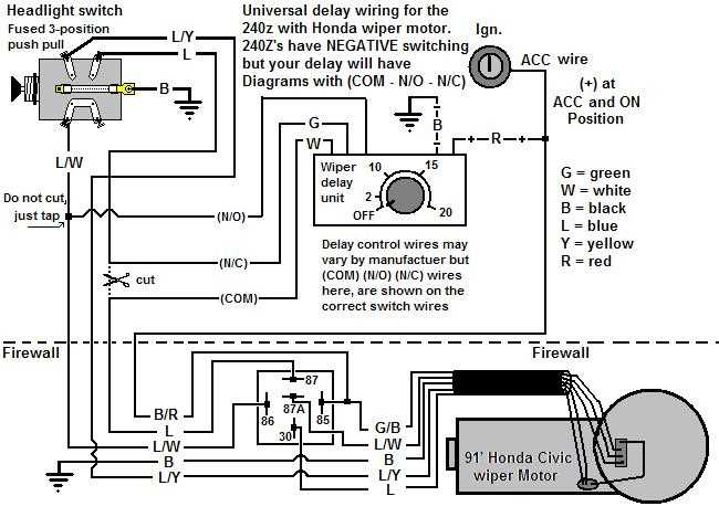
The wiper blades are the essential parts that come into direct contact with the windshield. They are responsible for clearing rain, snow, dust, and other debris from the windshield surface, improving visibility for the driver. Wiper blades are typically made of rubber or silicone and are attached to the wiper arms, which are connected to the wiper motor. It’s important to choose the correct size and type of wiper blades for your vehicle to ensure optimal performance.
4. Wiring harness:

The wiring harness connects all the electrical components of the wiper system, including the wiper switch, wiper motor, and power source. It consists of a series of wires with connectors that facilitate the flow of electrical current between the components. The wiring harness should be properly installed and routed to prevent any interference or damage to the wires, ensuring reliable and safe operation of the wiper system.
5. Fuse and relay:
To protect the wiper system from electrical faults and overloads, a fuse and relay are often included in the wiring diagram. The fuse acts as a safety device that will blow and interrupt the flow of current in case of a short circuit or excessive current draw. The relay, on the other hand, is an electromagnetic switch that controls the flow of current to the wiper motor. It allows the wiper switch to control the motor without directly handling the full power load.
By understanding the function and interconnection of these key components, you can create an effective universal wiper switch wiring diagram that ensures the reliable and efficient operation of your vehicle’s wiper system.
Step-by-step guide to wiring a universal wiper switch

Wiring a universal wiper switch can be a straightforward process if you follow the correct steps and have a clear understanding of the components involved. Here is a step-by-step guide to help you with the wiring process:
Step 1: Gather the necessary tools and materials
Before starting the wiring process, make sure you have all the necessary tools and materials. This may include a universal wiper switch, wire connectors, electrical tape, wire strippers, and a wiring diagram specific to your vehicle.
Step 2: Disconnect the battery
For safety purposes, it is important to disconnect the battery before working on any electrical components. Locate the battery in your vehicle and remove the negative terminal to prevent any accidental electrical discharge.
Step 3: Identify the switch’s wiring terminals
Refer to the wiring diagram specific to your vehicle and identify the different terminals on the universal wiper switch. These terminals may be labeled with letters or numbers and correspond to different functions such as power supply, park, low speed, high speed, and washer.
Step 4: Strip the wire ends
Using wire strippers, carefully strip the insulation off the wire ends that will be connected to the switch. It is recommended to strip about 1/4 inch of insulation to ensure a good connection.
Step 5: Connect the wires to the switch
Using wire connectors, connect each wire to its corresponding terminal on the universal wiper switch. Make sure to secure the connections tightly to ensure proper conductivity. It may be helpful to refer to the wiring diagram or a color-coding system to match the correct wires to their respective terminals.
Step 6: Test the wiper switch
Once all the wires are connected, it is important to test the wiper switch before finalizing the installation. Reconnect the battery and test each function of the switch to ensure it is working correctly. This may include testing the park, low speed, high speed, and washer functions.
Step 7: Secure the connections and reassemble
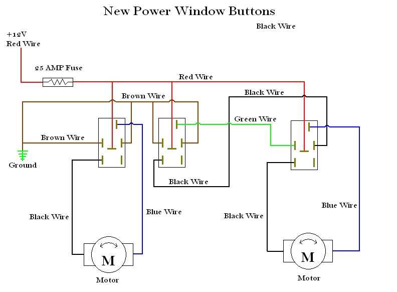
After confirming that the wiper switch is functioning properly, secure the wire connections with electrical tape or wire connectors. Make sure all the connections are properly insulated to prevent any electrical shorts. Finally, reassemble any panels or covers that were removed during the installation process.
Following these steps should help you successfully wire a universal wiper switch in your vehicle. It is important to always refer to the wiring diagram specific to your vehicle and take necessary safety precautions while working with electrical components.
Tips and tricks for troubleshooting a universal wiper switch wiring diagram
When working with a universal wiper switch wiring diagram, it’s important to follow a few tips and tricks to ensure that you troubleshoot any issues effectively. This can help you identify and fix any problems with the wiring and get your wiper switch functioning properly. Here are some useful tips:
- Double-check your connections: Before starting the troubleshooting process, make sure all your connections are secure and properly connected. Loose or incorrect connections can cause issues with the wiper switch.
- Use a multimeter: A multimeter is a valuable tool for troubleshooting electrical systems. Use it to check for continuity, resistance, and voltage at different points in the wiring diagram to identify any faulty components or connections.
- Inspect the wiring for damage: Carefully inspect the wires for any signs of damage such as fraying, cuts, or burns. Damaged wires can cause issues with the wiper switch. Replace any damaged wires as needed.
- Check the fuse: If the wiper switch is not working at all, check the fuse that powers the wiper system. A blown fuse can cause the switch to malfunction. Replace the fuse if necessary.
- Refer to the manufacturer’s instructions: If you’re having trouble understanding the universal wiper switch wiring diagram, consult the manufacturer’s instructions or manual. They will provide specific information about the wiring connections and troubleshooting steps for your particular switch model.
By following these tips and tricks, you can effectively troubleshoot a universal wiper switch wiring diagram and resolve any issues with your wiper switch. Remember to always exercise caution when working with electrical systems and consult a professional if you’re unsure about any steps or procedures.
Common Mistakes to Avoid When Wiring a Universal Wiper Switch
When wiring a universal wiper switch, it’s important to avoid certain common mistakes that can lead to malfunctions or even damage to the switch or the wiper system. Here are some key mistakes to avoid:
1. Incorrect Wiring Connections
One of the most common mistakes is connecting the wires to the wrong terminals on the switch or the vehicle’s wiring harness. It is crucial to carefully study the wiring diagram provided with the switch and make sure to match the correct wires to the corresponding terminals. Swapping wires or connecting them incorrectly can result in unexpected behavior or complete failure of the wiper system.
2. Improper Gauge Wire
Using wires that are either too thin or too thick can cause various issues. Thin wires may not be able to handle the current required by the wiper motor and may overheat, melt, or cause a voltage drop. On the other hand, using overly thick wires can be unnecessary and may create difficulties during installation. It is essential to use the appropriate gauge wire specified in the switch’s documentation to ensure proper functioning and avoid any electrical problems.
3. Neglecting Proper grounding
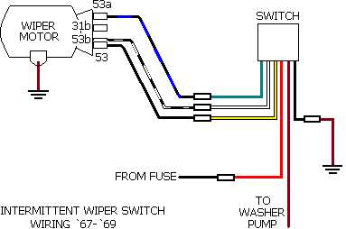
Proper grounding is essential for the reliable operation of the wiper system. Neglecting to connect the grounding wire or using a faulty ground connection can lead to all sorts of problems, including erratic wiper movement, motor overheating, or system failure. It’s crucial to ensure a clean and solid ground connection by following the manufacturer’s instructions and using suitable grounding points.
4. Using Incorrect Fuse Ratings
Fuses are crucial for protecting the wiper system from electrical faults and preventing damage. It’s important to use the correct fuse rating as recommended by the manufacturer to prevent overcurrent conditions. Using a fuse with too high a rating can leave the wiper system vulnerable to damage, while using a fuse with too low a rating can cause it to blow repeatedly, resulting in an unreliable wiper system.
5. Neglecting Proper Insulation
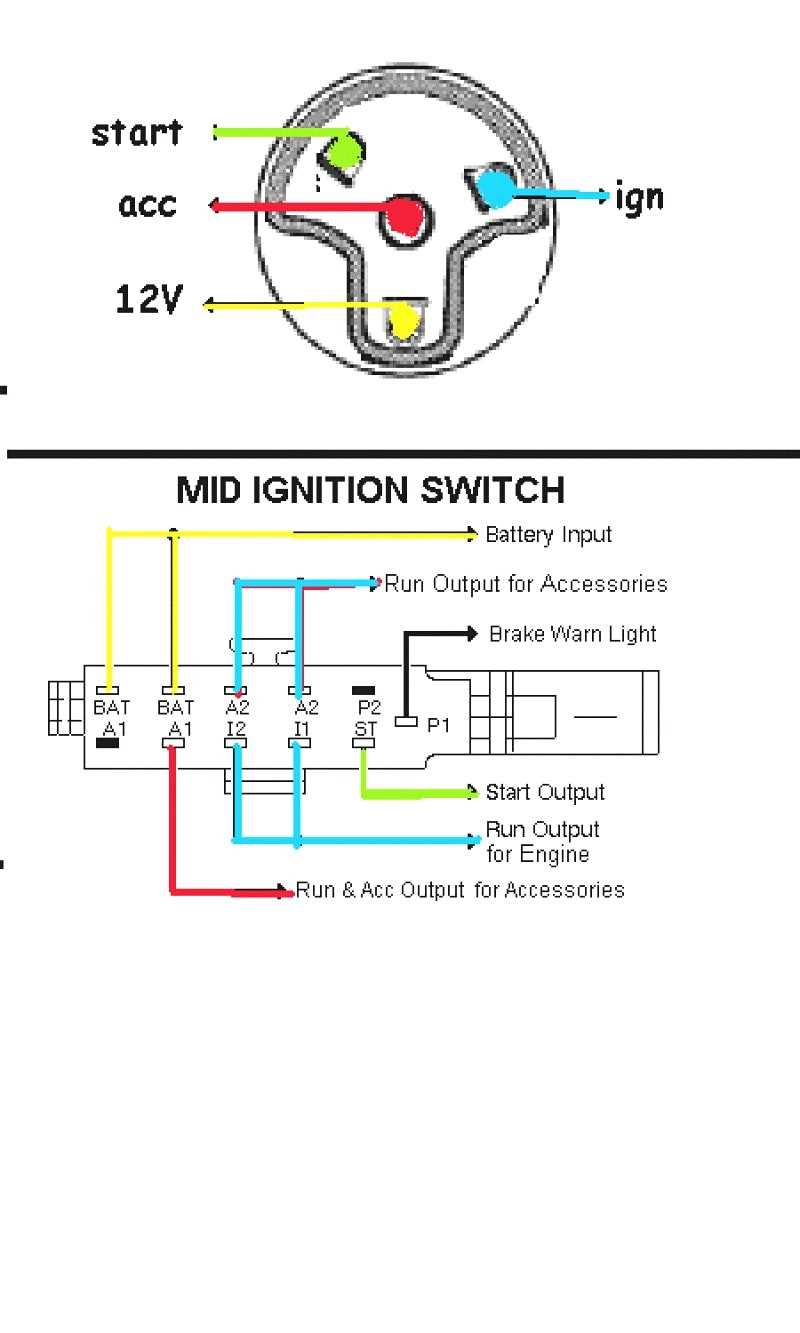
Insulation is vital for preventing short circuits, fires, and other electrical hazards. Failing to properly insulate the connections, especially in areas where wires come in contact with metal surfaces or other wiring, can lead to a host of issues. It is crucial to use appropriate insulation materials, such as electrical tape or heat shrink tubing, to protect the wires and ensure a safe and dependable wiper system.
By avoiding these common mistakes, you can ensure a successful wiring process and a reliable universal wiper switch that will provide smooth and efficient operation of your vehicle’s wiper system.
Q&A:
What are some common mistakes to avoid when wiring a universal wiper switch?
Some common mistakes to avoid when wiring a universal wiper switch include not properly grounding the switch, using incorrect wire sizes, not following the wiring diagram, and not securing the connections properly.
Why is it important to properly ground the universal wiper switch?
Properly grounding the universal wiper switch is important because it ensures that the switch functions correctly and prevents electrical issues such as short circuits or malfunctioning wipers.
How can using incorrect wire sizes affect the performance of the universal wiper switch?
Using incorrect wire sizes can lead to overheating, voltage drops, and possible wiring damage. It is important to use the right wire gauge as specified in the switch’s instructions to ensure safe and reliable operation.
Why is it necessary to follow the wiring diagram when installing a universal wiper switch?
Following the wiring diagram is necessary to ensure that all the connections are made correctly. It helps to avoid confusion and prevents accidental wiring mistakes that could lead to electrical problems.