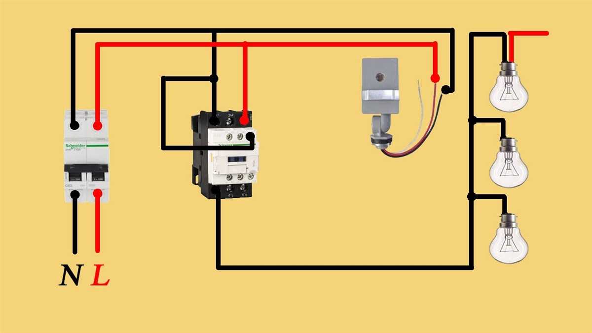
If you’re looking to install a GE lighting contactor, it’s important to familiarize yourself with the wiring diagram. A lighting contactor is a device that controls the operation of lighting circuits. It turns the lights on and off as needed, either manually or automatically. GE’s lighting contactors are known for their reliability and high performance, making them a popular choice in commercial and industrial settings.
The wiring diagram for a GE lighting contactor provides a visual representation of how the electrical connections should be made. It shows the location of each terminal, as well as how the different wires should be connected. Following the wiring diagram is crucial to ensure that the contactor functions properly and safely.
Typically, a GE lighting contactor will have a number of terminals, each serving a specific purpose. These terminals include power terminals, control terminals, and load terminals. The power terminals are where the incoming power from the electrical supply is connected. The control terminals are where the control switch or relay is connected to operate the contactor. The load terminals are where the lighting circuits are connected.
By referring to the GE lighting contactor wiring diagram, you can easily identify which wire goes where and make the necessary connections. This ensures that the contactor functions as intended, allowing you to control your lighting circuits efficiently and effectively. It also helps in troubleshooting any potential issues that may arise during installation or later on.
What is a GE lighting contactor wiring diagram?
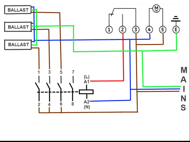
A GE lighting contactor wiring diagram is a visual representation of the electrical connections and components used in a lighting contactor system manufactured by General Electric (GE). The diagram provides a detailed illustration of how the contactor, switches, relays, and other electrical devices are connected together to control the operation of lighting fixtures.
The wiring diagram typically includes information such as the power sources, control circuit connections, load connections, and any auxiliary devices used in the system. It shows the different wires and terminals used, their color codes, and how they are connected to each other. This allows electricians and technicians to understand the wiring configuration and troubleshoot any issues that may arise during installation or maintenance.
The GE lighting contactor wiring diagram is an invaluable tool for electricians who work with lighting systems, as it provides a clear and concise illustration of how the system is wired. It can be used to ensure that the wiring connections are correct and to identify any potential wiring errors or problems. This can help prevent electrical malfunctions, improve the efficiency of the lighting system, and ensure the safety of both the electrician and the end-user.
Components of a GE lighting contactor wiring diagram

A GE lighting contactor wiring diagram is a visual representation of the electrical connections and components for a lighting contactor manufactured by GE. It provides a detailed overview of how the contactor is wired and how it interacts with other electrical devices in a lighting system. Understanding the different components of a GE lighting contactor wiring diagram is essential for proper installation and troubleshooting.
1. Contactors: The contactors are the main components of the lighting contactor wiring diagram. They are responsible for controlling the flow of electricity to the lighting circuits. The wiring diagram shows the connections and placement of the contactors, indicating the power input and output terminals.
2. Control circuits: The control circuits of a GE lighting contactor are used to operate the contactors. The wiring diagram illustrates how the control circuits are connected to the contactors and to other control devices, such as push buttons or timers. It shows the wiring of the control circuit components, including relays, switches, and interlock devices.
3. Power supply: The power supply is an important component of the lighting contactor wiring diagram. It provides the electrical energy needed to operate the contactors and control circuits. The wiring diagram indicates the source of power and the connections to the contactors and control circuits.
4. Lighting circuits: The lighting circuits are the circuits that supply power to the lighting fixtures. The wiring diagram shows the connections between the contactors and the lighting circuits. It indicates the number of lighting circuits, the wiring configuration, and the load distribution.
5. Protective devices: The protective devices are essential for the safe operation of the lighting contactor. The wiring diagram includes the placement and wiring of protective devices, such as fuses or circuit breakers. These devices help prevent overloads and short circuits, ensuring the protection of the contactors and the lighting system.
In summary, a GE lighting contactor wiring diagram provides a comprehensive visual representation of the electrical connections and components of a lighting contactor. It allows electricians and technicians to understand the wiring configuration, identify potential issues, and ensure proper installation and operation of the lighting system.
Main Power Supply
The main power supply is an essential component of any electrical system. It is responsible for delivering electricity to various electrical devices and components within a system. Without a reliable and stable power supply, the operation of the electrical system can be severely impacted.
In the context of GE lighting contactor wiring diagram, the main power supply is typically connected to the contactor through a dedicated circuit. This circuit is designed to handle the power requirements of the contactor and the associated lighting load. It is important to ensure that the main power supply is properly sized and rated to handle the expected load.
When wiring a GE lighting contactor, it is crucial to follow the manufacturer’s instructions and the applicable local electrical codes. The main power supply should be connected to the appropriate terminals on the contactor, ensuring proper polarity and tight connections. This will ensure a safe and reliable operation of the lighting system.
Additionally, it is recommended to install appropriate overcurrent protection devices, such as circuit breakers or fuses, in the main power supply circuit. These devices help protect the wiring and equipment from overloading and potential electrical hazards. The proper sizing and selection of these devices should be done in accordance with the electrical code and the specific requirements of the lighting system.
In conclusion, the main power supply is a crucial component in the wiring of a GE lighting contactor. It is responsible for delivering the necessary electrical power to the contactor and the lighting load. Proper installation, sizing, and protection of the main power supply are essential for the safe and reliable operation of the lighting system.
Control Circuit
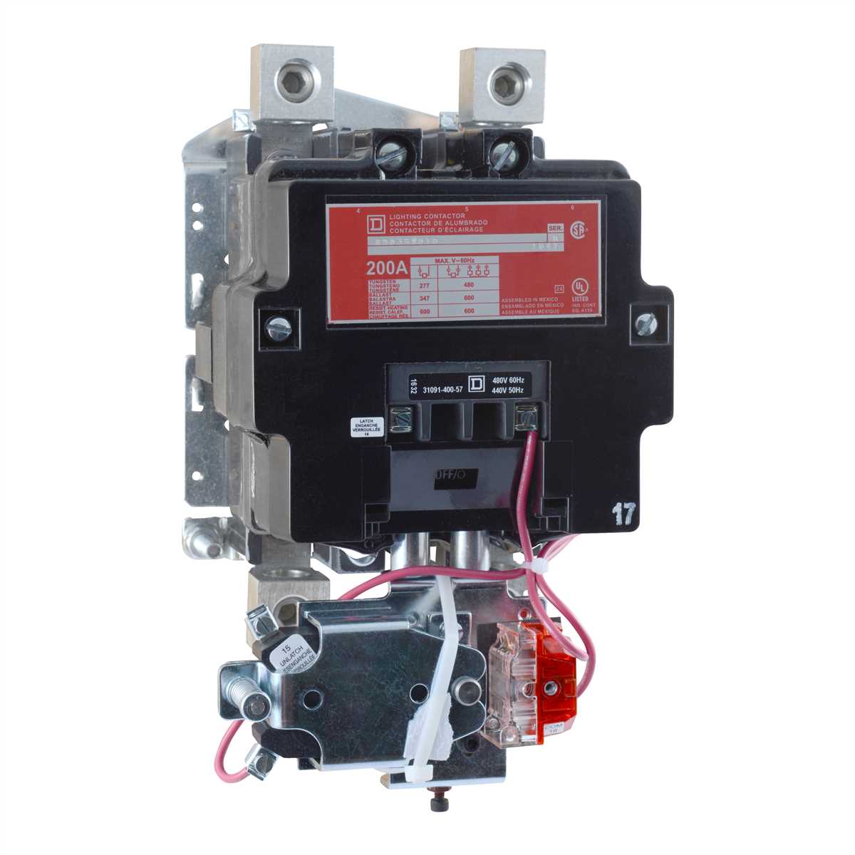
A control circuit is an essential part of a lighting contactor system. It is responsible for controlling when the contactor is energized or de-energized, allowing for the proper operation of the lighting system. The control circuit typically consists of various components, including switches, relays, and timers, that work together to control the flow of electrical current to the contactor coils.
One key component of the control circuit is a switch, which can be manually operated or controlled by an automated system such as a motion sensor or a photocell. The switch allows the user to manually turn the lights on or off, or it can automatically activate the contactor based on certain conditions, such as the presence of motion or the level of ambient light.
In addition to the switch, the control circuit may also include relays, which act as electromagnetic switches that can open or close the electrical circuit. Relays are often used to control a high-voltage circuit with a low-voltage signal, allowing for the safe and efficient operation of the lighting system. They are commonly used in conjunction with timers, which can be set to control when the contactor should be energized or de-energized at specific times.
The control circuit is typically wired using low-voltage wiring, which is safer and more practical than using high-voltage wiring for control purposes. The wiring is usually color-coded to differentiate between different circuits and to ensure proper installation and maintenance. Proper wiring and circuit identification are important to ensure the reliable and safe operation of the lighting contactor system.
In summary, the control circuit is a critical component of a lighting contactor system. It consists of switches, relays, and timers that work together to control when the contactor is energized or de-energized. The control circuit can be manually operated or automated, allowing for the convenient and efficient operation of the lighting system. Proper wiring and circuit identification are essential to maintain the reliability and safety of the system.
Lighting Circuit
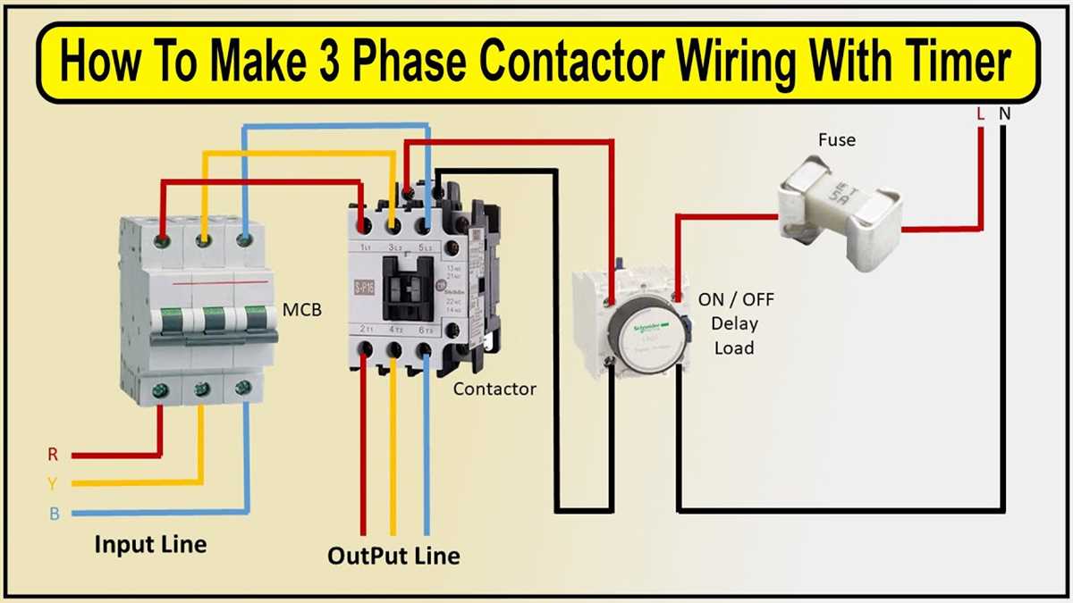
A lighting circuit is a system of electrical components that allows for the distribution and control of lighting in a building or space. It consists of various elements such as lighting fixtures, switches, wiring, and a power source. The circuit is designed to provide safe and efficient lighting by allowing individual control of different areas or zones.
The key components of a lighting circuit include:
- Power source: Usually an electrical panel or distribution board that supplies electricity to the circuit.
- Circuit breaker: A protective device that automatically shuts off the circuit in case of electrical faults or overloads.
- Wiring: Electrical cables and wires that connect the various components of the circuit.
- Switches: Devices that control the flow of electricity to the lighting fixtures. They can be simple on/off switches or more advanced dimmer switches.
- Lighting fixtures: The actual light sources such as bulbs, lamps, or LED strips that provide illumination in the space.
The wiring in a lighting circuit can be either radial or loop-in. In a radial circuit, the power source connects directly to the first lighting fixture, and then the wiring runs in a radial pattern to the subsequent fixtures. In a loop-in circuit, the power source connects to a junction box, and from there, each lighting fixture is connected to the next in a loop formation.
Proper wiring and installation of a lighting circuit are crucial for ensuring safe and efficient operation. It is important to follow electrical codes and guidelines when designing and installing the circuit. Additionally, regular maintenance and inspections are necessary to identify and address any issues or faults that may arise.
Overload protection
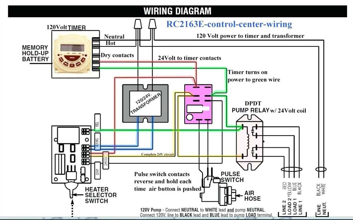
An overload protection is an essential component of any electrical system, including GE lighting contactors. Its main function is to prevent excessive current from flowing through the system, which can lead to overheating and potential damage or failure of the equipment.
GE lighting contactors are often used in applications where multiple lighting circuits need to be managed. These contactors are designed to handle high currents and provide a convenient way to control the lighting circuits. However, in order to prevent excessive current from flowing through these contactors, overload protection devices must be used.
There are several types of overload protection devices that can be used with GE lighting contactors, including thermal overload relays and electronic overload relays. Thermal overload relays are the most common type and they work by monitoring the motor temperature. If the temperature exceeds a certain threshold, the relay will trip and disconnect the motor from the power source.
Electronic overload relays, on the other hand, use electronic circuitry to monitor the current flowing through the contactor. These relays can be more precise and offer additional features such as adjustable trip settings and remote monitoring. They are often preferred in applications where precise control and monitoring are required.
It is important to correctly select and size the overload protection device for the specific application. The device should be capable of handling the maximum expected current without tripping prematurely, but also provide sufficient protection in case of a fault. Consulting the manufacturer’s guidelines and specifications is crucial in order to ensure proper selection and installation of the overload protection device.
Interlocks
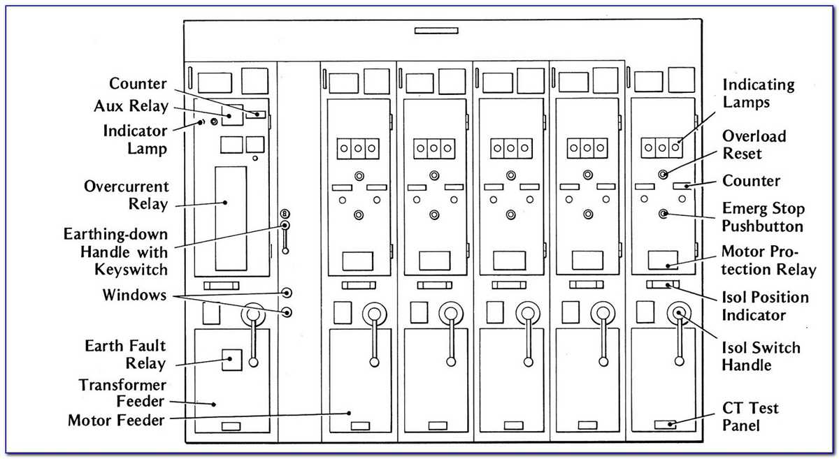
The interlock system plays a crucial role in ensuring the safe and efficient operation of GE lighting contactors. By implementing interlocks, potential hazards and accidents can be minimized, protecting both the equipment and the personnel working with it.
One common type of interlock used in lighting contactors is the mechanical interlock. This interlock mechanism physically prevents two conflicting actions from occurring simultaneously. For example, it can prevent opening a main disconnect switch while the lighting contactor is in a closed position, or vice versa.
Another type of interlock is the electrical interlock. This interlock utilizes electrical circuits to ensure that certain conditions are met before a specific action can be performed. An example of this would be requiring a certain voltage to activate the coil of the lighting contactor, ensuring that it cannot be accidentally energized.
Interlocks can also be used to coordinate the operation of multiple lighting contactors. For instance, if a system requires multiple contactors to control different sections of lighting, interlocks can be used to ensure that only one contactor is energized at a time. This prevents overloading of the electrical system and safeguards against potential damage.
Overall, interlocks provide an additional layer of safety and control in the operation of GE lighting contactors. Whether they are mechanical or electrical in nature, these interlocks help to prevent accidents, minimize damage, and ensure the efficient functioning of lighting systems.
Grounding
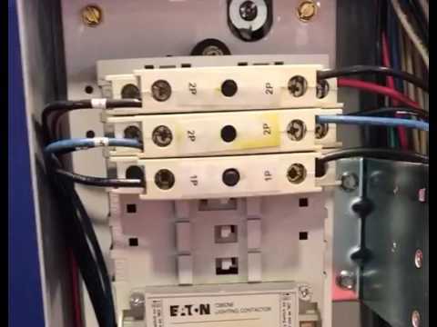
In any electrical system, grounding is an essential safety measure that helps protect people and property from electrical hazards. Grounding provides a low-resistance path for electrical current to flow in the event of a fault, helping to prevent electric shock and fires.
GE Lighting contactors are designed to be grounded in accordance with local electrical codes and regulations. The grounding connection for the contactor should be made to a dedicated grounding electrode, such as a metal water pipe or a grounding rod, depending on the specific requirements of the installation.
It is important to ensure that the grounding wire is properly sized and installed to carry the maximum fault current that could occur in the electrical system. This will help to guarantee that the grounding system can effectively dissipate dangerous electrical energy if a fault occurs.
Additionally, it is important to periodically inspect and test the grounding system to ensure its effectiveness. Grounding electrodes should be inspected for corrosion or damage, and connections should be checked for proper tightness. Testing should be conducted using specialized equipment to measure the resistance of the grounding system, ensuring that it meets the required criteria.
In conclusion, proper grounding is an essential part of the safe and reliable operation of GE Lighting contactors. It helps protect against electrical hazards and ensures that fault currents are safely directed away from sensitive equipment and personnel.