
If you own a John Deere 717A lawn mower or are considering purchasing one, it’s important to familiarize yourself with the different components of its deck. The deck is an integral part of the mower and is responsible for cutting, mulching, and discharging grass clippings. Understanding the deck diagram can help you properly maintain and troubleshoot any issues that may arise.
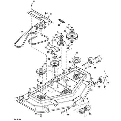
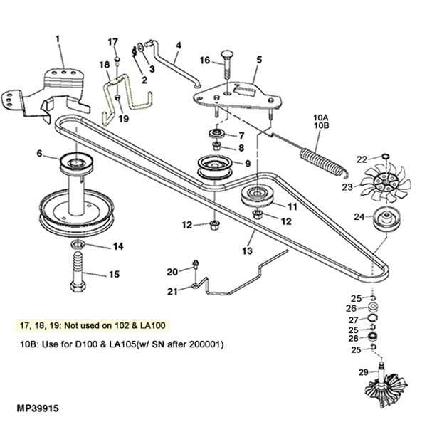
The John Deere 717A deck diagram provides a visual representation of all the key parts and their respective positions. The diagram typically includes labels for the spindle assemblies, blades, belt, deck shell, gauge wheels, and more. Each component plays a vital role in ensuring the mower operates efficiently and delivers a clean, even cut.
By studying the deck diagram, you can easily identify the location of each component and understand how they interact with one another. This knowledge can be helpful when it comes to replacing blades, inspecting the belt, or troubleshooting any potential problems. Being able to visually understand the deck’s anatomy can save you time and frustration when performing maintenance or repairs.
Whether you’re a seasoned lawn mower enthusiast or a first-time John Deere owner, taking the time to familiarize yourself with the deck diagram is a wise investment. It will empower you to confidently navigate the maintenance and operation of your John Deere 717A, ensuring optimal performance and longevity of your lawn mower.
What is a John Deere 717A deck diagram?
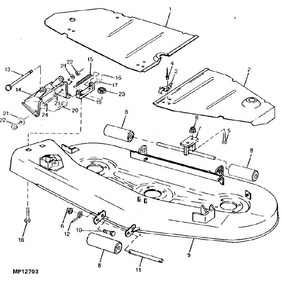
A John Deere 717A deck diagram is a visual representation of the deck components and their arrangement for a John Deere 717A mower. The diagram provides a detailed illustration of the deck’s structure, including the belt routing, blade spindle locations, and other essential elements.
The deck diagram is crucial for understanding the layout and assembly of the deck components, especially when it comes to maintenance and repair tasks. It serves as a reference guide for owners, technicians, and enthusiasts who wish to troubleshoot or replace certain deck parts.
Key components and features:
- Blade Spindles: The deck diagram shows the exact locations of the blade spindles, which are responsible for rotating the mower blades.
- Belt Routing: The diagram outlines the correct path for the mower deck belt, ensuring proper operation and power transmission.
- Blades: The diagram may indicate the type and position of the mower blades, which are crucial for cutting grass effectively.
- Adjustment Points: The diagram may highlight the various adjustment points on the deck, allowing owners to fine-tune the cutting height and levelness.
- Linkages and Pulleys: The diagram may include linkages and pulleys, which play a role in transferring power and controlling the deck’s movement.
By referring to a John Deere 717A deck diagram, owners and technicians can ensure proper maintenance and repair of the mower deck. It helps identify specific parts and their locations, aids in troubleshooting issues, and serves as a visual guide for assembly and disassembly processes. Overall, the deck diagram enhances the efficiency and effectiveness of deck-related tasks for the John Deere 717A mower.
The importance of a deck diagram
When it comes to maintaining and repairing a John Deere 717a deck, having a deck diagram can be an invaluable resource. This diagram provides an illustrated, detailed representation of the deck’s components, allowing users to easily identify and understand how each part functions within the overall mechanism. With this visual aid, users can confidently navigate through the deck’s complex structure and ensure proper assembly and disassembly.
One of the main advantages of a deck diagram is that it serves as a reference guide for troubleshooting or replacing specific parts. By referring to the diagram, users can quickly identify the exact location and orientation of each component, making it easier to diagnose and fix any issues that may arise. This can save valuable time and effort, preventing unnecessary disassembly or reassembly of the deck.
The deck diagram also helps users ensure proper maintenance and care of the deck. By understanding the layout and function of each component, users can accurately identify areas that require regular cleaning, lubrication, or adjustment. This helps prevent premature wear and tear and ensures the deck performs optimally for a longer period of time.
Overall, a deck diagram is an essential tool for anyone working with a John Deere 717a deck. It provides a clear visual representation of the deck’s components, aiding in troubleshooting, assembly, and maintenance. With its help, users can confidently tackle any task related to the deck, ensuring its optimal performance and longevity.
Understanding the John Deere 717A Deck Diagram
If you own a John Deere 717A mower and need to understand the deck diagram, this article will provide you with the information you need. The deck diagram is a visual representation of the mower’s cutting deck, showing the different components and how they are connected. It is an essential tool for troubleshooting and performing maintenance on your mower.
The deck diagram consists of several key components:
- Cutting Blades: The cutting blades are the main components responsible for cutting the grass. They are attached to the deck and rotate to cut the grass at the desired height.
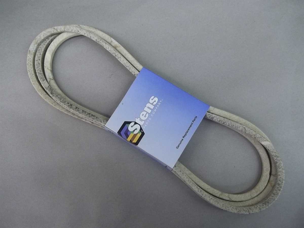
- Deck Belt: The deck belt is a crucial component that drives the cutting blades. It connects the engine pulley to the deck pulleys, transferring power from the engine to the blades.
- Deck Pulleys: The deck pulleys are responsible for guiding and tensioning the deck belt. They ensure that the belt stays in place and operates smoothly.
- Deck Spindles: The deck spindles are the bearings that hold the cutting blades in place. They allow the blades to spin freely and maintain proper alignment.
- Height Adjustment Mechanism: The height adjustment mechanism allows you to change the cutting height of the blades. It is usually operated by a lever or a knob, and it adjusts all the blades simultaneously.
In addition to these components, the deck diagram may also show other parts such as deck wheels, anti-scalp wheels, and spring tensioners. These additional components help ensure a consistent and even cut.
By referring to the deck diagram, you can easily identify and troubleshoot any issues with your John Deere 717A mower’s cutting deck. Whether you need to replace a worn-out belt, tighten a pulley, or adjust the cutting height, the deck diagram will guide you through the process and help you quickly get your mower back in working condition.
Components of the Deck
The deck of the John Deere 717a mower is composed of several key components that work together to provide a clean and precise cut. These components include:
- Blades: The blades are the cutting tools that are attached to the underside of the deck. They spin rapidly to cut the grass as the mower moves forward.
- Deck Spindle Assemblies: The deck spindle assemblies are responsible for rotating the blades. They connect the blades to the deck and provide the necessary power for cutting.
- Deck Belt: The deck belt is a long, durable belt that transfers power from the mower’s engine to the deck spindle assemblies. It ensures that the blades rotate at the correct speed to cut the grass effectively.
- Idler Pulleys: The idler pulleys help to create tension in the deck belt. They play a crucial role in maintaining the correct tension and preventing slippage.
- Deck Housing: The deck housing is the main structure that encloses and protects the blades, deck spindle assemblies, and other components. It is typically made of durable metal or reinforced plastic.
- Height Adjustment System: The height adjustment system allows the operator to raise or lower the deck to achieve the desired cutting height. It usually consists of a lever or knob that adjusts the position of the deck.
- Anti-Scalp Wheel: The anti-scalp wheel is a small wheel located on the deck that helps to prevent scalping. It ensures that the deck maintains an even height across uneven terrain, reducing the risk of damaging the grass.
Each of these components plays a vital role in the overall function and performance of the deck. Proper maintenance and regular inspection of these components are essential for ensuring optimal cutting performance and longevity of the deck.
Diagram Labels and Their Meanings
When looking at a John Deere 717A deck diagram, it is important to understand the various labels and their meanings. These labels provide valuable information about the different components and features of the deck, allowing users to identify and understand how each part works together to accomplish the desired cutting results.
Here are some key labels found in a John Deere 717A deck diagram:
- Cutting Deck: This label refers to the main structure of the deck that houses the cutting blades. It is responsible for supporting the blades and directing the flow of grass clippings.
- Blade Spindles: These labels indicate the locations of the blade spindles, which are the rotating components that hold the cutting blades in place. They allow the blades to spin and cut the grass efficiently.
- Idler Pulley: This label points to the idler pulley, which is responsible for maintaining proper tension on the deck belt. It helps to ensure smooth operation and optimal performance of the cutting blades.
- Deck Belt: This label refers to the belt that connects the engine to the cutting deck. It transfers power from the engine to the blades, enabling them to rotate and cut the grass.
- Anti-Scalp Wheels: These labels indicate the locations of the anti-scalp wheels, which help prevent the deck from scalping the ground when mowing uneven terrain. They provide additional support and stability to the deck.
- Height Adjustment Lever: This label points to the lever that allows users to adjust the cutting height of the deck. It enables users to customize the height of the grass being cut to achieve their desired lawn appearance.
Understanding these diagram labels and their meanings is essential for maintaining and troubleshooting the John Deere 717A deck. By familiarizing yourself with the components and their functions, you can ensure proper operation and extend the lifespan of your equipment.
How to Use the Deck Diagram
When it comes to maintaining and repairing your John Deere 717a deck, having a deck diagram can be incredibly helpful. A deck diagram provides a visual representation of the various components and parts of the deck, allowing you to easily identify and locate specific parts when needed. Knowing how to use the deck diagram effectively can save you time and frustration when working on your mower deck.
Step 1: Familiarize Yourself with the Diagram
Before you begin using the deck diagram, take some time to familiarize yourself with it. Pay close attention to the different symbols and labels used in the diagram, as these will help you identify the various parts and components. It’s also helpful to have a basic understanding of the terminology used in relation to mower decks, such as the spindle, belt, blades, and pulleys.
Step 2: Identify the Part or Component You Need to Work On
Once you’ve familiarized yourself with the deck diagram, you can start using it to identify the specific part or component you need to work on. Use the labels and symbols provided in the diagram to locate the part and determine its position in relation to other components in the deck. This will help you properly identify and remove the part for repair or replacement.
Step 3: Refer to the Diagram for Assembly and Disassembly
If you need to disassemble or reassemble your deck, the deck diagram can serve as a valuable reference. Follow the diagram to ensure that you correctly remove and install each part, making note of any specific instructions or order of operations. This will help ensure that your deck is properly put together and functions as intended.
Step 4: Use the Diagram to Troubleshoot Issues
When you encounter issues with your deck, such as abnormal noises, poor cutting performance, or sudden stops, the deck diagram can help you troubleshoot the problem. By referring to the diagram, you can visually inspect the various parts and components, checking for any damage, misalignment, or wear. This can help you pinpoint the source of the problem and determine the appropriate course of action for repair.
In conclusion, the deck diagram for your John Deere 717a can be a valuable tool when it comes to maintaining, repairing, and troubleshooting your mower deck. By familiarizing yourself with the diagram and using it effectively, you can save time, avoid mistakes, and ensure that your deck is in optimal working condition.
Step-by-step instructions for the John Deere 717a deck diagram
In order to properly understand the John Deere 717a deck diagram, it is important to follow step-by-step instructions. This will ensure that you have a clear understanding of the various components and their placement within the deck.
Step 1: Familiarize Yourself with the Diagram
Begin by taking a close look at the deck diagram. Identify the different parts and components that are labeled. Pay close attention to any numbers or letters associated with each part, as these will be important for referencing later on.
Step 2: Identify the Deck Belt Path
Next, locate the deck belt path on the diagram. This will typically be indicated by a bold line or arrows. Take note of how the belt wraps around various pulleys and other components. This will help you understand how to properly install or replace the deck belt.
Step 3: Determine the Blade Configuration
Look for the blade configuration on the deck diagram. This will show you the number and placement of the cutting blades. Pay attention to any instructions or notes regarding blade removal or replacement.
Step 4: Locate the Spindle Assembly
Find the spindle assembly on the deck diagram. This is the part that connects the deck belt to the cutting blades. Make sure you understand its location and how it fits into the overall deck structure.
Step 5: Refer to the Key
If there is a key provided with the deck diagram, refer to it for additional information. The key may provide explanations for various symbols or labels used in the diagram.
Step 6: Take Measurements

Measure any specific dimensions indicated on the diagram. This will help ensure proper placement and alignment of the deck components.
Step 7: Consult the Owner’s Manual
If you still have questions or need further clarification, consult the owner’s manual for the John Deere 717a or reach out to a qualified technician for assistance. They will be able to provide additional guidance specific to your model and deck configuration.
By following these step-by-step instructions, you will be able to effectively interpret the John Deere 717a deck diagram and confidently maintain or repair your deck. Remember to always prioritize safety and consult professional help when needed.
Troubleshooting common issues using the diagram
In order to troubleshoot common issues with the John Deere 717A deck, it is important to understand the various components and their functions as depicted in the deck diagram:
- Blades: Check for any damage or dullness in the blades. Dull blades can cause uneven cutting and require sharpening or replacement.
- Spindles: Inspect the spindles for any signs of wear or damage. Loose or damaged spindles can affect the deck’s operation and may need to be replaced.
- Belts: Examine the belts for any signs of wear or damage. Worn or damaged belts can cause the blades to malfunction and may need to be replaced.
- Pulleys: Check the pulleys for any signs of wear or damage. Faulty pulleys can cause belt slippage and affect the deck’s performance.
- Deck housing: Inspect the deck housing for any cracks, dents, or other damage. Damaged deck housing can affect the overall performance and may require repairs or replacement.
When troubleshooting common issues, refer to the diagram to identify any potential problems and compare them to the components described above. Ensure that all components are properly connected and functioning as intended.
It is recommended to follow the manufacturer’s guidelines for maintenance and servicing of the John Deere 717A deck. Regular cleaning, lubrication, and inspection of the components can help prevent issues and ensure optimal performance.
By utilizing the deck diagram and following proper maintenance procedures, users can effectively troubleshoot common issues and keep their John Deere 717A deck in good working condition.