When it comes to electrical wiring, understanding the basics is crucial. One common type of electrical wiring is the single phase AC wiring. This type of wiring is commonly used in residential and small commercial buildings. Understanding the single phase AC wiring diagram is essential for anyone in the electrical field, as it allows for proper installation and troubleshooting of electrical systems.
In a single phase AC wiring system, the electrical power is transmitted using two wires: the live wire, also known as the phase wire, and the neutral wire. The live wire carries the electrical current from the power source to the load, while the neutral wire provides a return path for the current back to the power source. This creates a complete circuit and allows for the flow of electrical energy.
It is important to note that the single phase AC wiring system utilizes a single phase voltage, which means that the voltage oscillates between positive and negative cycles. This alternating current (AC) is commonly used because it is more efficient for long-distance transmission and can be easily transformed to various voltage levels.
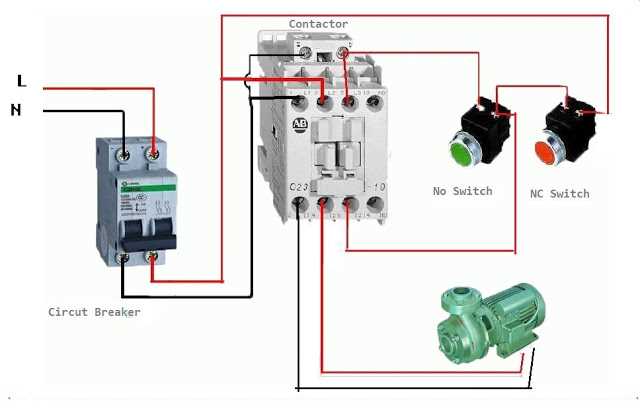
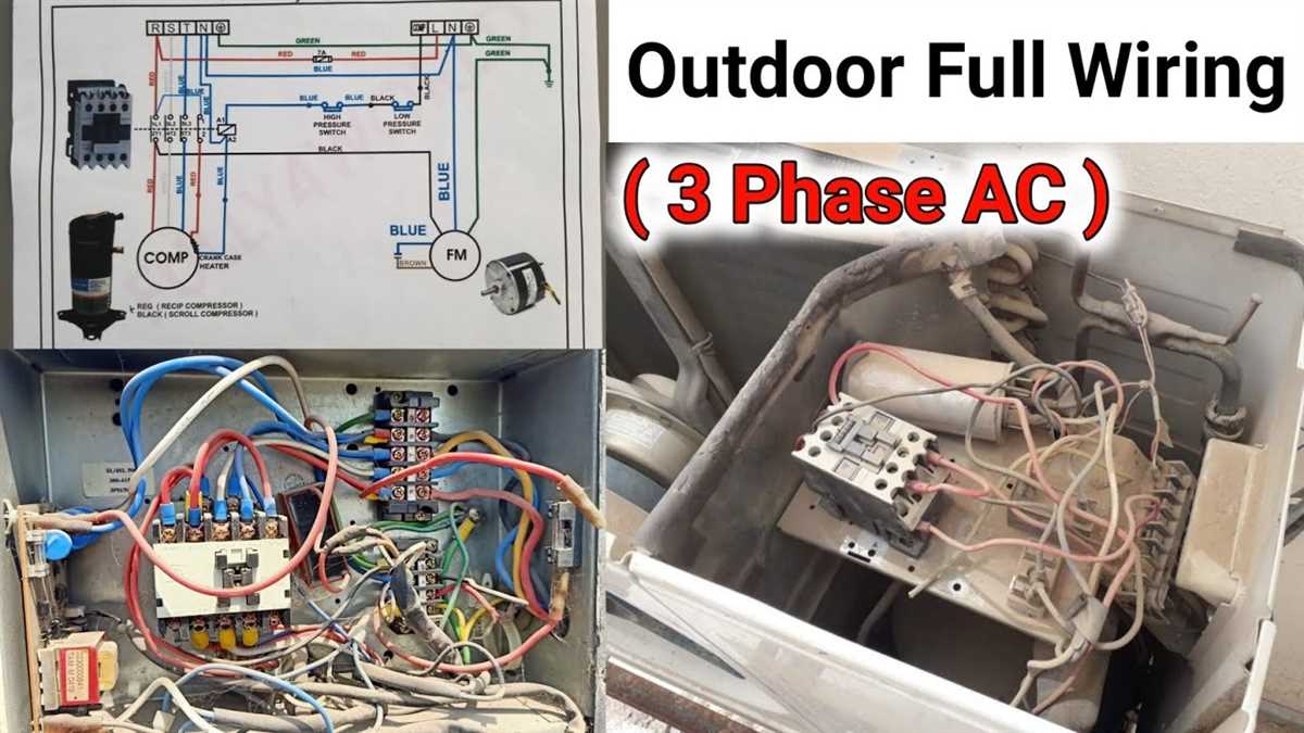
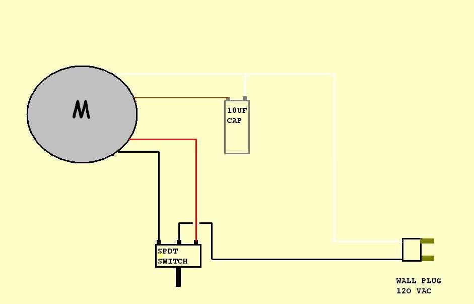
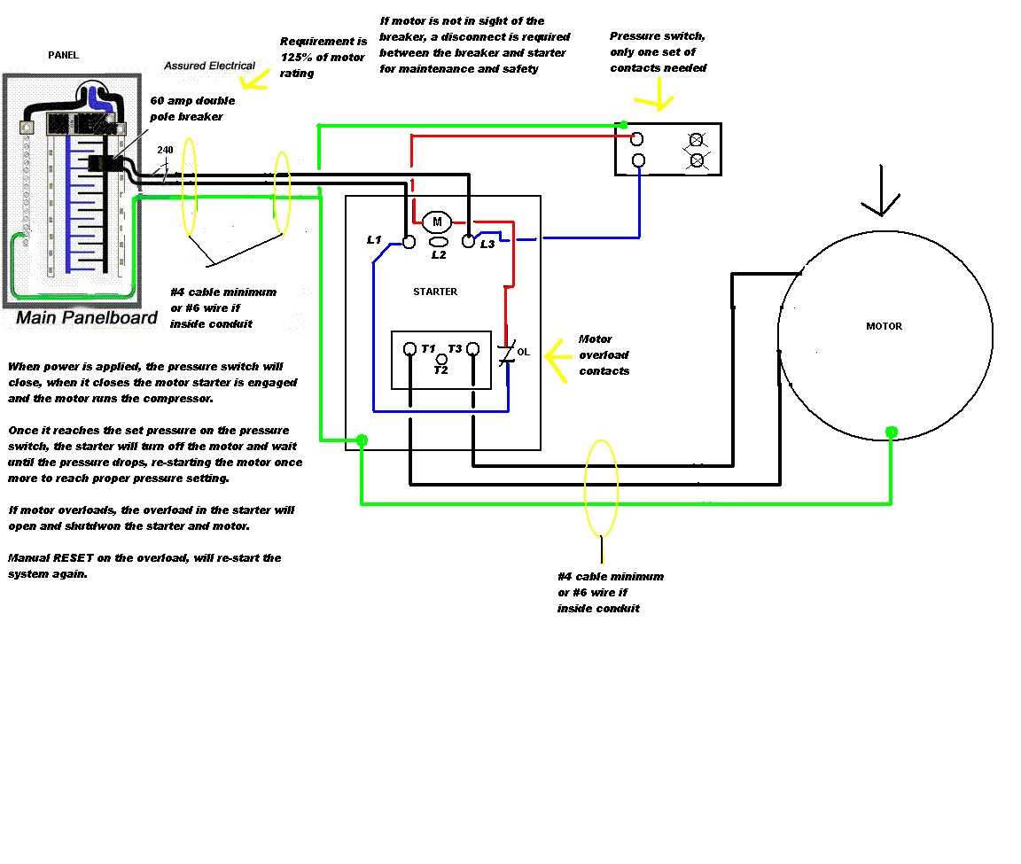
When looking at a single phase AC wiring diagram, you will typically see symbols representing the power source, load, switches, and various electrical components. The diagram will show the connection points and the flow of electrical current. By understanding this diagram, electricians can properly wire the system and troubleshoot any issues that may arise.
Understanding Single Phase AC Wiring Diagrams
Single-phase AC wiring diagrams are essential for understanding the electrical connections in a single-phase AC system. These diagrams provide a visual representation of the circuit and show how the various components are connected. A single-phase AC system consists of a power source, such as a generator or utility company, and loads, such as appliances or motors, which use the electrical power.
In a single-phase AC wiring diagram, the power source is usually represented by a waveform, such as a sine wave, and labeled as either “L” or “N” to indicate the live or neutral wire. The loads are connected to the power source through switches, fuses, circuit breakers, and various types of electrical outlets. The diagram also includes symbols for transformers, capacitors, and other components used in the system.
The wiring diagram helps electricians and technicians understand how the electrical system functions and troubleshoot any issues that may arise. By following the diagram, they can identify the correct connections, ensure proper grounding, and verify that the system meets safety and regulatory requirements. It also helps in the installation process, as it provides a blueprint for the electrical wiring layout.
Overall, understanding single-phase AC wiring diagrams is crucial for anyone working with electrical systems. It enables the safe and efficient installation, maintenance, and repair of single-phase AC circuits, ensuring that electrical power is properly distributed to the loads and avoiding potential hazards or equipment damage.
What is Single Phase AC?
Single phase AC (alternating current) refers to an electrical power supply that consists of a single sinusoidal voltage waveform. It is commonly used in residential and small commercial applications where the power demand is relatively low. This type of electrical supply is different from three-phase AC, which consists of three sinusoidal waveforms.
Single phase AC is typically supplied at a frequency of 50 or 60 Hz, depending on the region. The voltage levels can vary, but the most common voltage for residential applications is 120 or 240 volts. In contrast, three-phase AC systems provide higher power capacity and are commonly used in industrial and commercial applications.
Single phase AC is generated and distributed using transformer-based systems. It is commonly used for lighting, heating, and small appliances in homes, offices, and shops. The wiring diagram for single phase AC may include a main circuit breaker, a meter, a distribution board, and individual circuits for various electrical loads.
Understanding the wiring diagram for single phase AC is important for electricians and individuals who need to perform electrical installations or repairs. It helps identify the different components and connections in the electrical system, ensuring safe and efficient operation. Proper wiring and connection of single phase AC circuits are essential to prevent electrical hazards and maximize the lifespan of electrical equipment.
The Basics of Single Phase AC Wiring

Single-phase AC wiring is a common electrical setup used in residential and small commercial buildings. It involves the distribution of electrical power using only one alternating current (AC) waveform. Understanding the basics of single-phase AC wiring is essential for anyone involved in electrical installations or troubleshooting.
One of the key components in single-phase AC wiring is the voltage source, which is typically provided by the utility company. The voltage supplied to buildings is usually 120 or 240 volts, depending on the location and electrical requirements. This voltage is delivered through two main wires: a “hot” wire, which carries current from the power source to the load, and a neutral wire, which completes the circuit and returns the current back to the source.
In single-phase AC wiring, the hot wire is typically colored black, while the neutral wire is colored white or gray. It’s important to note that the hot wire carries the full voltage, while the neutral wire is connected to ground potential. This wiring configuration allows for the safe and efficient delivery of electricity to various electrical devices and appliances.
Additional components are often used in single-phase AC wiring to provide protection and control. These may include circuit breakers, fuses, and switches. Circuit breakers, for example, are designed to automatically interrupt the flow of electricity in the event of an overload or short circuit. Fuses serve a similar purpose but need to be replaced manually once they blow.
It’s also worth mentioning that single-phase AC wiring may employ different types of connections depending on the specific application. For example, a common connection used in residential houses is the split-phase system, where the incoming voltage is split into two 120-volt circuits that can power various household appliances separately. Other types of single-phase AC connections include the center-tapped transformer configuration and three-wire systems.
Overall, understanding the basics of single-phase AC wiring is crucial for ensuring safe and efficient electrical installations. It’s important to follow electrical codes and regulations when working with single-phase AC wiring, as improper installation can lead to electrical hazards and damage to electrical equipment.
Components of Single Phase AC Wiring Diagram
The single phase AC wiring diagram consists of several key components that work together to ensure the efficient and safe distribution of electrical power. These components include:
- Power Source: The power source, typically a generator or utility grid, supplies the electrical energy to the system. It is connected to the wiring system through a meter, which measures the amount of electricity consumed by the load.
- Distribution Panel: The distribution panel, also known as the main breaker panel or fuse box, receives the electrical power from the power source and distributes it to various circuits in the building. It contains circuit breakers or fuses that protect the circuits from overloads and short circuits.
- Circuit Breakers: Circuit breakers are switches that automatically interrupt the flow of electricity in a circuit when the current exceeds a certain limit. They are designed to protect the wiring and electrical devices from damage caused by overloads or short circuits. Circuit breakers can be reset after they trip, unlike fuses which need to be replaced.
- Wiring: The wiring provides the path for the electricity to flow from the power source to the load. It consists of conductors, typically copper or aluminum wires, that are enclosed in protective sheathing. The wiring is labeled with different colors to identify the function of each wire.
- Outlets and Switches: Outlets and switches are the points of connection for electrical devices in a building. Outlets provide power to appliances and devices, while switches control the flow of electricity to lights and other fixtures. They are connected to the wiring system and are typically installed in walls or ceilings.
- Grounding System: The grounding system provides a path for the electrical current to flow into the ground, preventing electrical shock and reducing the risk of fire. It consists of a grounding rod or plate, grounding wires, and grounding electrodes connected to the wiring system. The grounding system also helps to stabilize the voltage and reduce electrical noise.
In summary, the components of a single phase AC wiring diagram work together to ensure the safe and efficient distribution of electrical power in a building. From the power source to the distribution panel, circuit breakers, wiring, outlets, switches, and grounding system, each component plays a crucial role in the electrical system’s functionality and safety.
Common Single Phase AC Wiring Configurations

In the field of electrical wiring, single phase AC (alternating current) is widely used for residential and small commercial applications. Understanding the different wiring configurations is important for electricians and anyone working with electrical systems.
Split-phase wiring: This is the most common single phase AC wiring configuration used in residential homes. It involves a single phase power supply that is split into two separate 120V circuits, each with its own hot wire and shared neutral wire. This configuration allows for the use of 240V appliances (such as electric stoves and dryers) while still providing 120V power for lighting, outlets, and other devices.
Single-phase three-wire wiring: This configuration is commonly used in small commercial buildings and provides two separate 120V circuits, each with its own hot wire and shared neutral wire. However, unlike split-phase wiring, there is no 240V power supply available.
Single-phase four-wire wiring: This configuration is typically used in larger commercial and industrial settings. It includes two hot wires, a neutral wire, and a ground wire. The two hot wires provide 120V power and can be used in combination to provide 240V power when needed. The neutral wire is used to complete the circuit, while the ground wire provides safety by grounding any electrical faults.
These are just a few examples of common single phase AC wiring configurations. It’s important to always follow electrical codes and safety guidelines when working with electrical systems to ensure proper installation and prevent accidents or damage. Consulting with a qualified electrician is always recommended when in doubt.
Step-by-Step Guide to Reading and Interpreting Single Phase AC Wiring Diagrams
Single phase AC wiring diagrams serve as a visual representation of the electrical connections and components in a single phase AC circuit. These diagrams are commonly used in the electrical industry to aid in the installation, troubleshooting, and repair of single phase AC equipment. Understanding how to read and interpret these diagrams is essential for anyone working with single phase AC systems.
Step 1: Familiarize Yourself with the Symbols and Notations
Before diving into a single phase AC wiring diagram, it is important to become familiar with the symbols and notations used in these diagrams. Common symbols may include lines to represent wires, circles to represent junctions or connections, and various shapes to represent components such as switches, motors, and transformers. Understanding the meaning of these symbols and notations is crucial for accurately interpreting the wiring diagram.
Step 2: Identify the Power Source and Distribution
The first step in reading a single phase AC wiring diagram is identifying the power source and distribution. This can usually be found at the top or side of the diagram and is represented by a line or set of lines with a voltage rating. This section will show how the power is distributed throughout the circuit and may include components such as main breakers, fuses, or disconnect switches.
Step 3: Trace the Circuit Path
Once the power source and distribution have been identified, the next step is to trace the circuit path. Start at the power source and follow the lines and symbols to understand the flow of electricity through the various components. This will help you recognize how the circuit is connected and which components are in series or parallel.
Step 4: Analyze the Components
As you trace the circuit path, pay attention to the various components represented in the diagram. These may include switches, motors, capacitors, resistors, or transformers. Each component will have its own symbol or notation, and understanding their function and operation is crucial for accurately interpreting the wiring diagram. Use the provided information or refer to equipment manuals to gain a deeper understanding of each component’s role in the circuit.
Step 5: Follow the Wiring Connections
Finally, examine the wiring connections between the various components in the circuit. This is typically shown as lines between the symbols or notations. Pay attention to the colors and thickness of the lines, as they may indicate different wire types or sizes. Understanding these connections will give you a clear picture of how the electrical current flows through the circuit and helps in troubleshooting issues or making modifications.
Reading and interpreting single phase AC wiring diagrams may seem overwhelming at first, but with practice and a solid understanding of the symbols, notations, and components, it becomes easier to accurately analyze and troubleshoot electrical circuits.
Troubleshooting Single Phase AC Wiring Issues

When dealing with single phase AC wiring issues, it is important to follow a systematic troubleshooting approach in order to identify and resolve the problem. Here are some steps to help you troubleshoot common issues:
- Check for power supply: Start by checking if there is a power supply to the circuit. Make sure the circuit breaker is not tripped and that the power supply is turned on.
- Inspect wiring connections: Examine all the wiring connections to ensure they are properly connected and tightened. Loose or faulty connections can lead to poor electrical performance or complete failure.
- Test voltage: Use a multimeter to measure the voltage at different points in the circuit. This will help you identify any voltage drop or irregularities that may indicate a problem.
- Check for damaged wiring: Inspect the wiring for any signs of damage, such as frayed insulation or exposed wires. Damaged wiring can cause electrical shorts or other issues.
- Test components: Test the various components in the circuit, such as switches, outlets, and motor windings, to ensure they are functioning correctly. Faulty components can lead to issues with the overall circuit.
- Consult a professional: If you are unable to identify or resolve the issue on your own, it is best to seek the assistance of a qualified electrician. They have the knowledge and experience to troubleshoot and repair more complex wiring issues.
By following these troubleshooting steps, you can effectively identify and resolve single phase AC wiring issues. Remember to always prioritize safety and consult a professional when needed.
Q&A:
Why is my single phase AC not working?
There could be several reasons why your single phase AC is not working. It could be due to a faulty power supply, a blown fuse, a tripped circuit breaker, a malfunctioning capacitor, or a problem with the motor or compressor. It is best to consult a professional electrician to diagnose and fix the issue.
What should I do if there is no power in one of the outlets?
If there is no power in one of the outlets, you can try resetting the circuit breaker associated with that outlet. If that doesn’t work, check for loose or damaged wiring connections. If everything seems to be fine, you may need to call an electrician to troubleshoot and fix the issue.
Why does my single phase AC keep tripping the circuit breaker?
If your single phase AC keeps tripping the circuit breaker, it could be due to overloading. Check if you are using too many appliances on the same circuit. It could also be a sign of a faulty electrical component or a short circuit. Consult an electrician to identify and resolve the problem.
What causes overheating in a single phase AC?
Overheating in a single phase AC can be caused by a variety of factors, including clogged or dirty air filters, a malfunctioning fan motor, a refrigerant leak, or a faulty compressor. It is important to address the issue promptly to prevent further damage to the unit and to ensure efficient cooling.
Why is my single phase AC emitting a burning smell?
If your single phase AC is emitting a burning smell, it could indicate an electrical problem. It may be due to overheated or damaged electrical components, loose wiring connections, or an overloaded circuit. It is essential to turn off the AC immediately, unplug it, and contact a professional electrician to investigate and resolve the issue.
What are common troubleshooting steps for single phase AC wiring issues?
Some common troubleshooting steps for single phase AC wiring issues include checking for loose or damaged connections, testing the voltage at different points in the circuit, inspecting the circuit for any damaged or frayed wires, and checking the functionality of switches and breakers. It is also important to ensure that the correct voltage is being supplied to the circuit and that the wiring is properly grounded. If these steps do not resolve the issue, it may be necessary to consult a professional electrician.