The Solera smart arm is an innovative technology that provides automated control for RV awnings. With its advanced features and user-friendly interface, the Solera smart arm allows RV owners to easily extend and retract their awnings with just a push of a button.
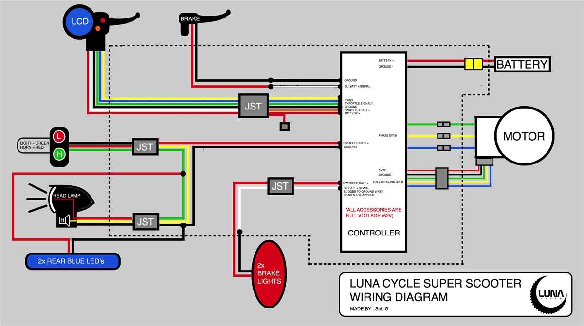
One of the key components of the Solera smart arm system is the wiring diagram. This diagram provides a visual representation of how the different electrical components of the smart arm are connected. It includes information on the wiring connections, fuses, and relays that are used to control the motor and other functionalities of the smart arm.
The wiring diagram is an essential tool for RV owners, as it helps them understand the electrical system of the Solera smart arm and troubleshoot any issues that may arise. By referring to the wiring diagram, RV owners can easily identify and fix wiring problems, ensuring that their awnings function properly at all times.
Overall, the Solera smart arm wiring diagram is a crucial resource for RV owners who want to make the most of their awning system. It provides a clear and concise representation of the electrical connections and components of the smart arm, allowing for easy installation, maintenance, and troubleshooting.
Overview
The Solera smart arm wiring diagram provides a detailed schematic of the electrical connections and components used in the Solera smart arm system. This diagram is essential for understanding the wiring layout and ensuring proper installation and maintenance of the system.
The Solera smart arm system is a cutting-edge technology that utilizes sensors and actuators to automate various tasks in an industrial or commercial setting. This system is designed to improve the efficiency and productivity of operations by streamlining processes and reducing manual labor.
The wiring diagram includes all the necessary information for connecting the various components of the smart arm system, such as the sensors, actuators, control panel, and power supply. It illustrates the connections between these components and provides clear labeling and instructions for proper wiring.
By following the Solera smart arm wiring diagram, technicians and installers can ensure that the system is installed correctly and all connections are made according to specifications. This diagram also serves as a valuable reference tool for troubleshooting and maintenance, allowing technicians to easily identify and resolve any issues that may arise with the system.
Components
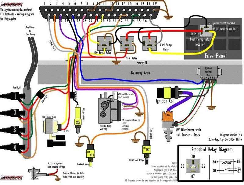
In the Solera smart arm wiring diagram, there are several components that play a crucial role in the overall functionality of the system. These components include:
1. Solera Smart Arm
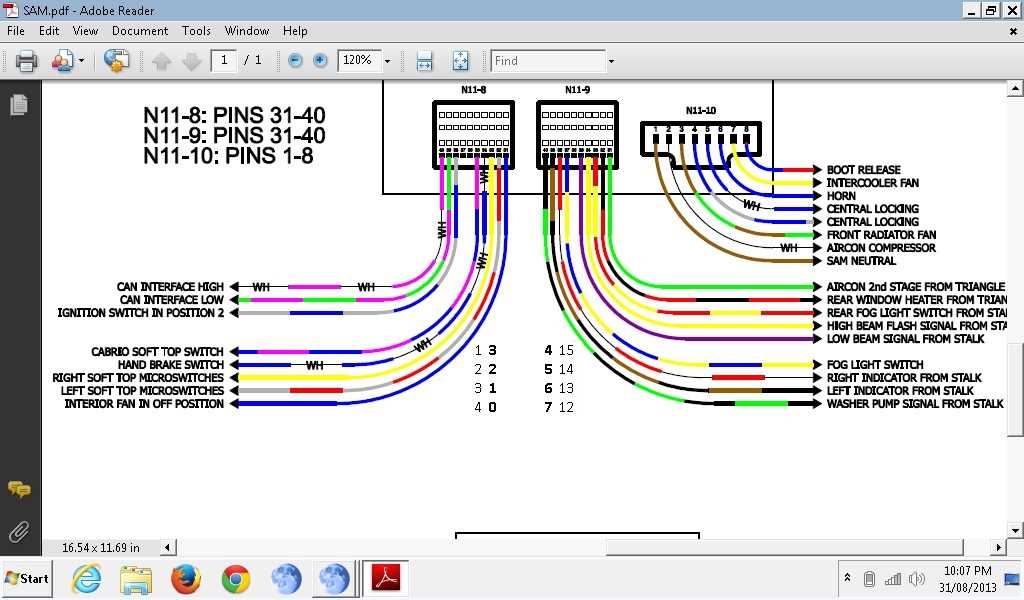
The Solera smart arm is the main component of the system and serves as the primary interface between the wiring and the external devices. It is equipped with various sensors, actuators, and communication modules, allowing it to interact with the surrounding environment.
2. Sensors:
- Position sensors: These sensors are responsible for detecting the current position and orientation of the smart arm. They provide crucial feedback to the system, enabling precise control and manipulation.
- Force sensors: Force sensors measure the amount of force exerted by the smart arm during operation. This information is used for safety purposes and to ensure proper functioning of the system.
- Proximity sensors: Proximity sensors detect the presence of objects or obstacles near the smart arm. They help prevent collisions and ensure safe operation in various environments.
3. Actuators:
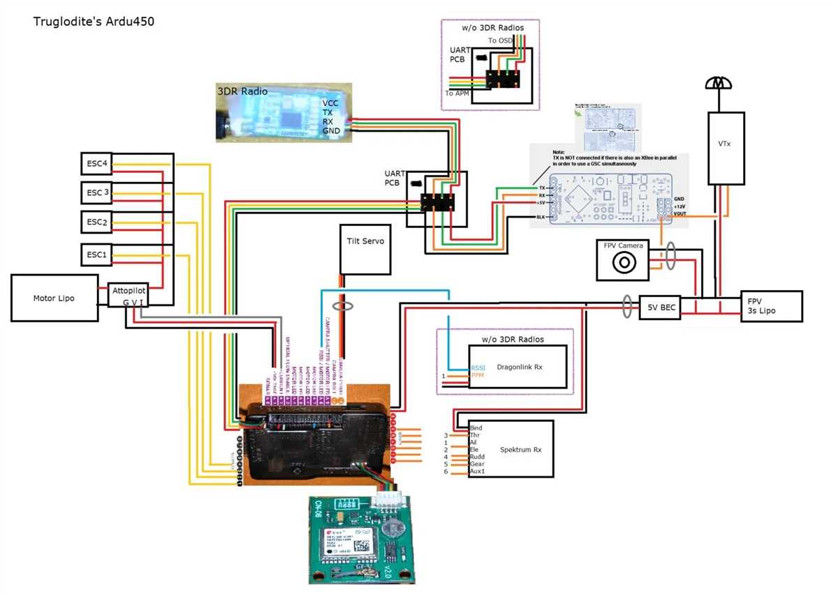
- Electric motors: Electric motors are responsible for generating the necessary torque and movement required by the smart arm. They can control the arm’s joints and enable precise positioning and manipulation.
- Grippers: Grippers are used for grasping and holding objects. They can be pneumatic or electrically operated, depending on the specific application requirements.
4. Communication Modules:
- Wiring harness: The wiring harness connects all the components of the smart arm and facilitates the transfer of electrical signals and power between them.
- Microcontroller: The microcontroller acts as the brain of the system, processing data from sensors, controlling actuators, and managing communication with external devices.
- Communication protocols: The smart arm may use various communication protocols, such as Ethernet, Wi-Fi, or Bluetooth, to communicate with other devices or the central control system.
By understanding the different components of the Solera smart arm wiring diagram, it becomes easier to visualize how the system functions and how each component contributes to its overall operation and functionality.
Connections
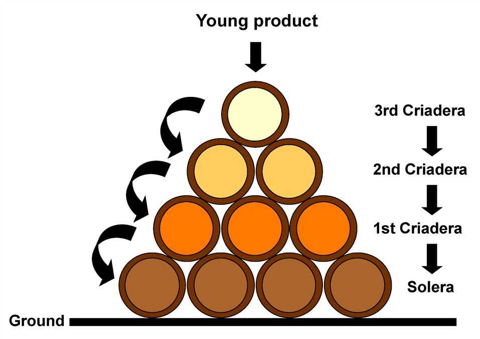
The Solera smart arm wiring diagram provides a detailed overview of the various connections required to set up and operate the smart arm system. These connections play a crucial role in ensuring the proper functioning of the smart arm and its integration with other components in the system.
Power connection: The smart arm requires a power source to operate. The wiring diagram includes the connection points for the power supply, ensuring that the smart arm is powered correctly.
Control signal connection: The smart arm is controlled through a control signal. The wiring diagram indicates the connections for the control signal, allowing the smart arm to receive and respond to commands from the control system.
Sensor connections: The smart arm may be equipped with various sensors to enable it to interact with its environment. The wiring diagram outlines the connections for these sensors, ensuring that they are correctly integrated into the smart arm system.
Communication connections: In some cases, the smart arm may need to communicate with other devices or systems. The wiring diagram includes the connections for communication interfaces, such as USB or Ethernet, enabling the smart arm to exchange data with other components or transmit information to a central system.
Motor connections: The smart arm is typically equipped with motors to enable its movement. The wiring diagram specifies the connections for these motors, ensuring that they receive the correct signals to execute the desired movements.
Installation
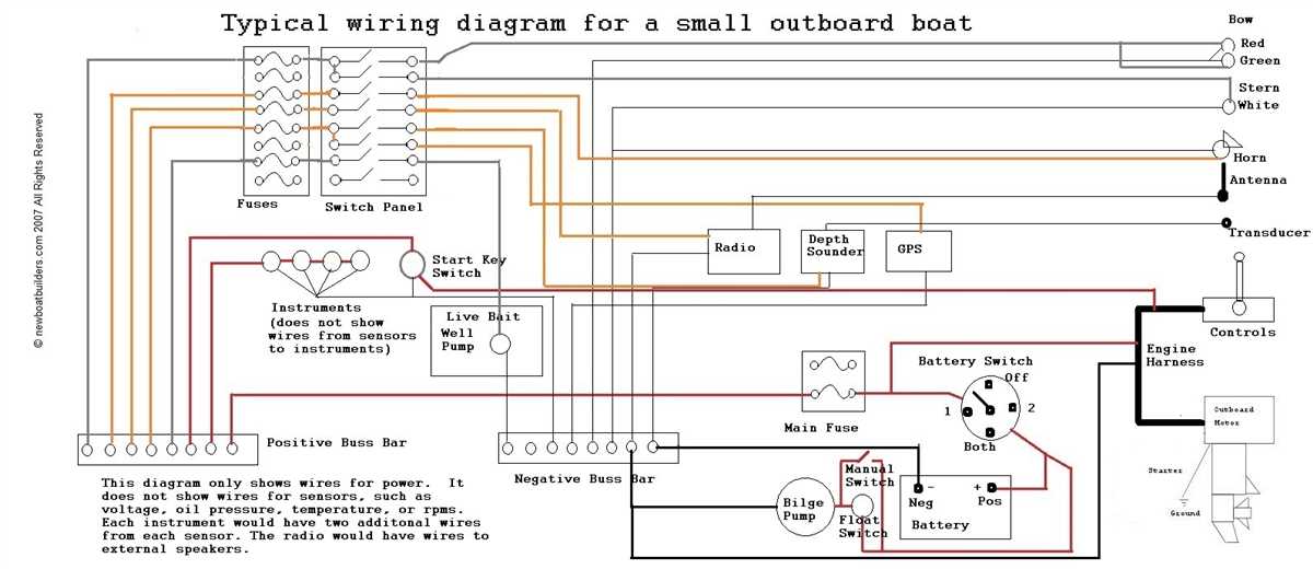
The Solera smart arm is a revolutionary device that allows for improved control and efficiency in home automation systems. Before installing the Solera smart arm, it is important to carefully review the wiring diagram and ensure that all connections are made correctly.
Step 1: Begin by locating the main control panel for your home automation system. This is where the Solera smart arm will be connected. Ensure that the power to the control panel is turned off before proceeding.
Step 2: Using the provided wiring diagram, identify the necessary connections for the Solera smart arm. This will include connections for power, communication, and any additional devices or sensors that will be used in conjunction with the smart arm.
Step 3: Once the necessary connections have been identified, carefully attach the wiring to the appropriate terminals on the control panel. It is important to ensure that all connections are secure and tight to prevent any potential issues or malfunctions.
Step 4: After all connections have been made, it is recommended to double-check the wiring diagram and connections to ensure accuracy. Once verified, the power to the control panel can be turned back on.
Step 5: Finally, test the Solera smart arm and all connected devices to ensure proper functionality. This may include activating different controls, testing sensors, and verifying communication between the smart arm and the control panel.
By following these installation steps and taking care to ensure proper wiring, the Solera smart arm can be successfully integrated into your home automation system, allowing for improved control and efficiency.
Troubleshooting
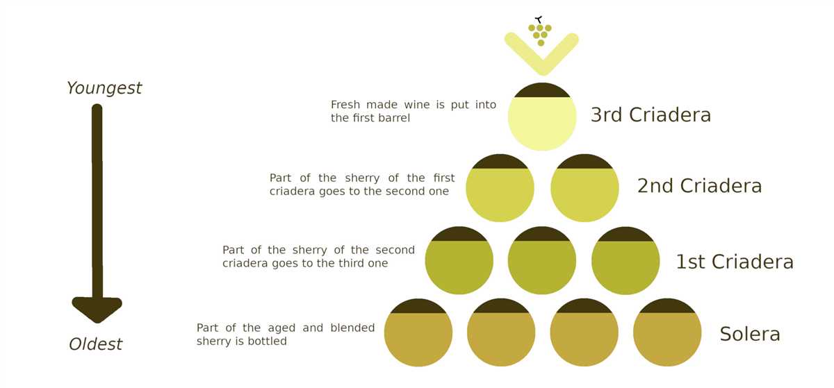
If you are experiencing issues with your Solera smart arm wiring, here are some troubleshooting steps you can take to resolve the problem:
1. Check the power supply
Make sure that the power supply to the smart arm is properly connected and providing the correct voltage. Inspect the wiring and connections for any damage or loose connections.
2. Verify the control signals
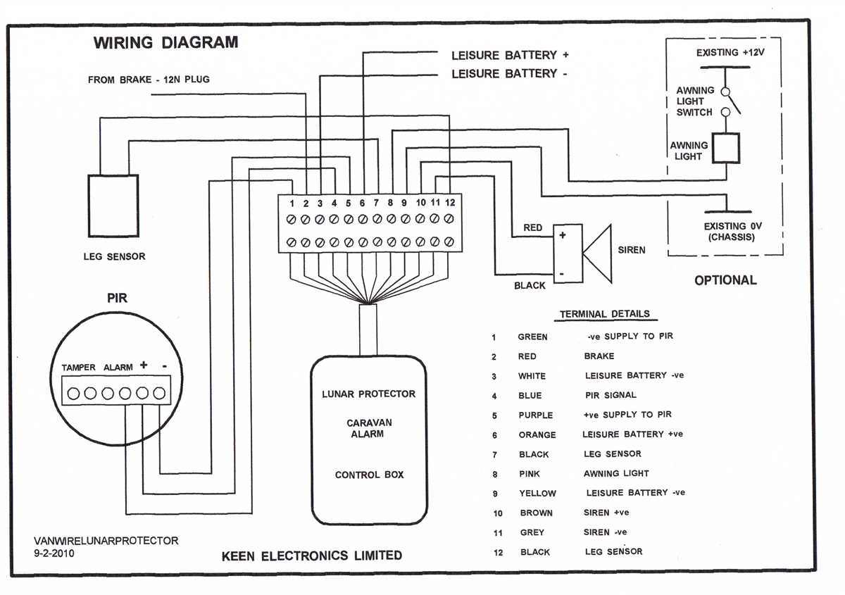
Check if the control signals from the controller to the smart arm are being correctly transmitted. Use a multimeter or oscilloscope to measure the voltage levels of the control signals and ensure they are within the expected range.
3. Examine the smart arm components
Inspect the smart arm for any visible signs of damage or wear. Pay close attention to the wiring, connectors, and actuators. Replace any faulty components as necessary.
4. Reset the smart arm
If the smart arm is not responding or functioning correctly, try resetting it. Refer to the user manual or documentation provided by the manufacturer for instructions on how to reset the smart arm.
5. Consult the Solera support team
If you have tried the above troubleshooting steps and are still unable to resolve the issue, contact the Solera support team. They will have more in-depth knowledge of the smart arm wiring and can provide further assistance.
Conclusion
Troubleshooting issues with Solera smart arm wiring can seem daunting, but by following these steps and seeking assistance when needed, you can ensure that your smart arm functions optimally. Always refer to the manufacturer’s documentation and seek professional help if necessary.