
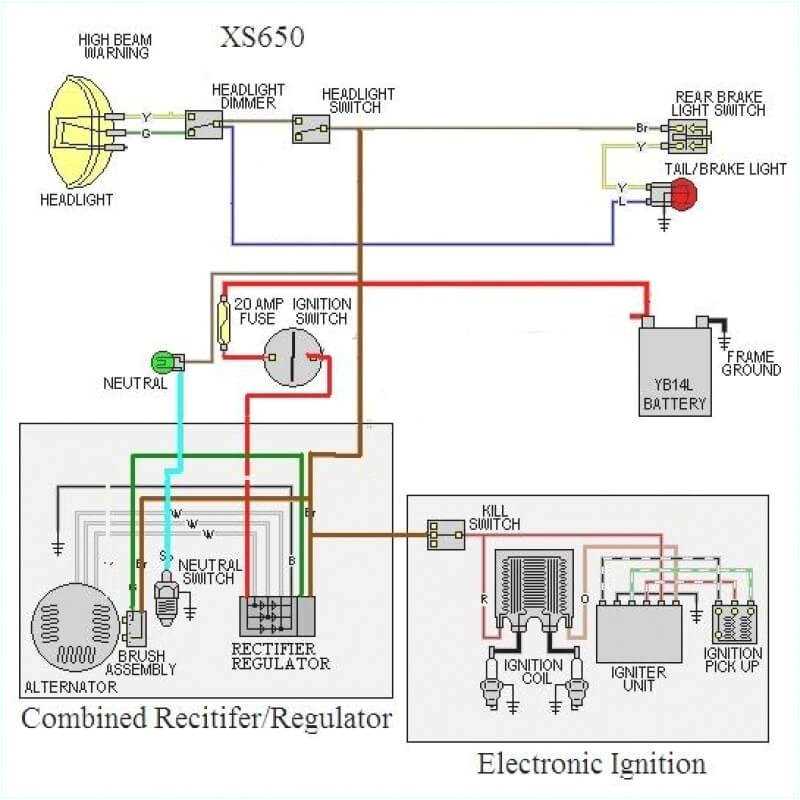
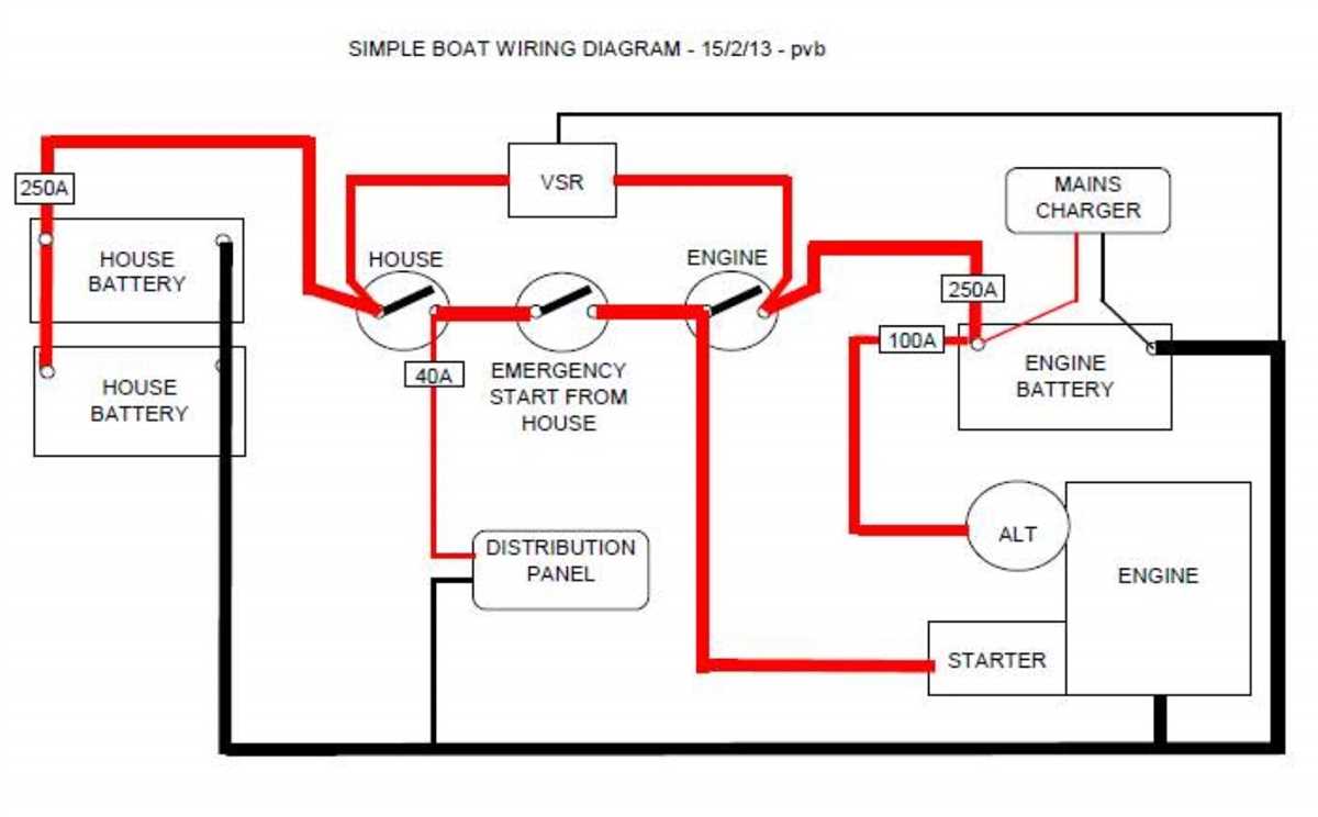
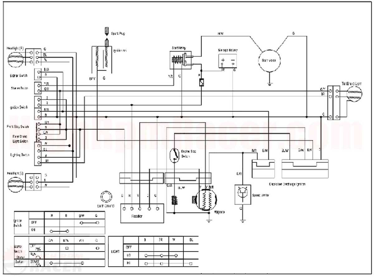
Wiring is an essential part of any electrical system. It is the process of connecting various components and devices to allow the flow of electricity. Whether it’s a simple light switch or a complex industrial automation system, understanding the basics of wiring schematics is crucial for any electrician or DIY enthusiast. A wiring schematic, also known as a circuit diagram, is a visual representation of the electrical connections and components in a system.
A basic wiring schematic typically includes symbols and lines to represent different electrical components and how they are connected. These symbols can include switches, outlets, lights, motors, and more. The lines in a wiring schematic indicate the paths through which electricity flows, and the connections between the components.
By studying a wiring schematic, you can easily understand how a circuit works and troubleshoot any issues that may arise. It allows you to identify the different components, their functions, and how they interact with each other. This knowledge is essential for diagnosing and repairing electrical problems, ensuring the proper installation of new devices, and ensuring the safety of the electrical system as a whole.
Learning to read a basic wiring schematic is a fundamental skill for anyone working with electricity. Whether you’re an electrician, an engineer, or just someone interested in DIY projects, understanding the basics of wiring schematics will give you the confidence to tackle electrical tasks and projects with ease. So, if you’re ready to embark on a journey into the world of electrical systems, grab a wiring schematic and start exploring the fascinating connections that power our world.
What is a Basic Wiring Schematic and How Does it Work?
A basic wiring schematic is a diagram that shows the connection and arrangement of electrical components in a system. It provides a visual representation of how the wires, switches, and other components are connected to each other, allowing technicians and engineers to understand the system and troubleshoot any issues that may arise.
In a basic wiring schematic, each electrical component is represented by a symbol or notation, such as a line for a wire, a circle for a lamp, or a switch for an on/off control. These symbols are then connected by lines to indicate the flow of electricity through the system. The schematic also includes labels or numbers to identify specific wires or components.
A basic wiring schematic works by providing a clear and concise illustration of the electrical connections in a system. This allows technicians to understand how electricity flows through the system and how different components interact with each other. By following the lines and symbols in the schematic, technicians can locate potential problem areas and make the necessary repairs or adjustments.
For example, if a light in a room is not working, a technician can consult the wiring schematic to trace the path of the electrical current and identify any potential issues, such as a faulty switch or a broken wire. This saves time and effort by providing a roadmap for troubleshooting and avoiding unnecessary guesswork.
Overall, a basic wiring schematic is an essential tool in the field of electrical engineering and repair. It helps technicians understand and analyze electrical systems, allowing them to diagnose and fix problems efficiently and safely.
Understanding the Basics of Electrical Wiring
Electrical wiring is a fundamental aspect of any electrical system. It refers to the interconnected system of conductors and devices that carry and distribute electricity throughout a building or structure. Having a basic understanding of electrical wiring is important for anyone working with or around electricity, as it allows for safe and effective troubleshooting, repairs, and installations.
Wiring Schematic:
A wiring schematic, also known as a circuit diagram, is a visual representation of an electrical circuit. It shows the connections between various electrical components and the flow of electricity through the circuit. By studying a wiring schematic, electricians and technicians can determine how a circuit is set up and identify any potential issues or malfunctions.
Conductors:
Conductors are materials that allow the flow of electrical current. In electrical wiring, conductors are typically made of copper or aluminum. They come in various forms, such as wires and cables, and are used to carry electricity from the power source to electrical devices or appliances. Understanding how to properly choose and install the right type and size of conductor is crucial for ensuring the safe and efficient operation of an electrical system.
Devices:
Electrical devices refer to the various components and equipment that are connected to an electrical system. This can include outlets, switches, circuit breakers, and lighting fixtures, among others. Each device has its own specific wiring requirements and functions, and understanding how to correctly wire and connect these devices is essential for maintaining the integrity and functionality of an electrical system.
In conclusion, having a basic understanding of electrical wiring is essential for anyone working with or around electricity. Knowing how to read wiring schematics, choose and install conductors, and wire devices properly will ensure the safe and effective operation of an electrical system. Whether you’re a homeowner looking to make simple electrical repairs or a professional electrician, taking the time to learn and understand the basics of electrical wiring is a valuable investment.
Components of a Basic Wiring Schematic
In electrical systems, a wiring schematic is a diagram that shows the connections and layout of the various components in a circuit. A basic wiring schematic includes several key components that are essential for the proper functioning of the circuit.
Power Supply:
The power supply is the source of electrical energy that drives the circuit. It can be an AC (alternating current) or DC (direct current) power supply, depending on the requirements of the circuit. The power supply is usually depicted by a symbol such as a battery or a wall outlet in the wiring schematic.
Switches:
Switches are devices that control the flow of electrical current in a circuit. They can be simple on/off switches or more complex ones that allow for different modes of operation. Switches are represented by various symbols in the wiring schematic, depending on their type and function.
Wires and Conductors:
Wires and conductors are used to connect the various components in the circuit. They provide a pathway for the flow of electricity. Different types of wires and conductors are used depending on the current and voltage requirements of the circuit. In the wiring schematic, wires are represented by lines with various symbols indicating their type and size.
Components:
Components refer to the various devices and elements that are connected in the circuit. This can include resistors, capacitors, diodes, transistors, and other electronic components. Each component has a specific function and is represented by a unique symbol in the wiring schematic. The connections between the components are shown by lines or dots in the diagram.
Ground and Earth Connections:
Ground and earth connections are important for safety and proper functioning of the circuit. The ground connection provides a reference point for the circuit’s voltage, while the earth connection ensures that any excess electrical charges are safely discharged into the ground. These connections are represented by special symbols in the wiring schematic.
Overall, a basic wiring schematic provides a visual representation of the various components and connections in a circuit. It helps in understanding the circuit’s structure, troubleshooting any issues, and ensuring the safe and efficient operation of the electrical system.
Step-by-Step Guide to Creating a Basic Wiring Schematic
Creating a basic wiring schematic is an important skill for anyone working with electrical systems. Whether you’re an electrician, an engineer, or a DIY enthusiast, having a clear and accurate wiring diagram can help you understand and troubleshoot electrical circuits. Here is a step-by-step guide to creating a basic wiring schematic.
Step 1: Identify the Circuit
The first step in creating a wiring schematic is to identify the circuit you want to diagram. Determine the purpose and components of the circuit. This can include switches, outlets, lights, motors, and any other electrical devices connected to the circuit. Make a list of these components and their connections to understand how the circuit functions.
Step 2: Gather Information
Next, gather all the necessary information to create your wiring schematic. This includes the voltage and current ratings of the circuit, the wire sizes and types used, and any other specifications that are relevant to the electrical installation. It’s also helpful to have a rough sketch or plan of the physical layout of the circuit to guide your diagram.
Step 3: Start the Schematic
Begin creating your wiring schematic by drawing a diagram of the circuit’s main components. Use symbols and labels to represent each component, such as switches, lights, and outlets. Connect the components with lines to show the flow of electricity and indicate the wiring connections between them. Be sure to use the correct symbols and follow established conventions for clarity and consistency.
Step 4: Add Details
As you progress with your wiring schematic, add more details to the diagram. Include information such as wire colors, wire numbers, and terminal connections. Label each component and wire with its corresponding name or number for easy identification. This will make it easier to understand and troubleshoot the circuit later on.
Step 5: Organize the Diagram
Once you have completed the basic wiring schematic, organize the diagram in a clear and logical manner. Arrange the components and wires so that the diagram flows from left to right or top to bottom. Use colors and shading to highlight different sections or groups of components. Consider using a table or grid format for complex circuits to make the diagram more organized and readable.
By following these steps, you can create a basic wiring schematic that accurately represents the electrical circuit you are working with. Remember to review and double-check your diagram for accuracy before using it for wiring or troubleshooting. With practice, you will become more proficient in creating wiring schematics and gain a deeper understanding of electrical systems.
Common Mistakes to Avoid in Basic Wiring Schematics
When it comes to creating basic wiring schematics, it’s important to be aware of common mistakes that can lead to electrical hazards or malfunctioning circuits. By understanding these mistakes and taking steps to avoid them, you can ensure a safe and efficient electrical system for your project. Here are some common mistakes to be mindful of:
1. Lack of Proper Grounding
One of the most common mistakes in basic wiring schematics is the lack of proper grounding. Grounding is essential for electrical safety as it provides a path for electrical currents to flow safely into the ground in the event of a fault or short circuit. Without proper grounding, there is a risk of electrical shocks or damage to equipment. Always ensure that all grounding connections are correctly made and properly connected to a grounding electrode.
2. Incorrect Wire Size
Another common mistake is using incorrect wire sizes for the intended load. Using wires that are too small can result in overheating and potentially lead to circuit damage or even fire. On the other hand, using wires that are too large is not only wasteful but can also cause compatibility issues with connectors or terminals. It’s crucial to refer to the appropriate wire size chart or consult a professional electrician to determine the correct wire size for the load.
3. Ignoring Electrical Codes and Regulations
Ignoring electrical codes and regulations is a significant mistake that can have severe consequences. Electrical codes are in place to ensure the safety and reliability of electrical systems. Failure to follow these codes can not only result in electrical hazards but may also lead to legal and insurance issues. Always research and comply with the applicable electrical codes and regulations for your location or consult with a licensed electrician.
4. Lack of Proper Labeling
Proper labeling is essential for understanding and troubleshooting a wiring schematic. It’s important to label all wires, connectors, and components to avoid confusion and ensure easy identification. Neglecting proper labeling can lead to mistakes during installation, repairs, or maintenance, causing unnecessary downtime and potential safety risks. Take the time to label all components and connections clearly using standardized labels or color-coding.
5. Failing to Test and Verify
Lastly, a common mistake is failing to test and verify the wiring schematic before finalizing the installation. This can lead to undetected faults or errors, which may cause issues down the line. Always perform thorough testing and verification of the wiring schematic to ensure correct connections, proper functionality, and safety. Use multimeters, circuit testers, or other appropriate tools to check for continuity, voltage, and proper operation.
By avoiding these common mistakes and taking the necessary precautions, you can ensure a safe, reliable, and efficient electrical system when working with basic wiring schematics.
Benefits and Applications of Basic Wiring Schematics
Basic wiring schematics are essential tools for anyone involved in electrical work or troubleshooting. They provide a concise and organized representation of an electrical circuit, making it easier to understand and work with. Here are some of the key benefits and applications of using basic wiring schematics:
1. Clear Visualization:
Basic wiring schematics present information in a visual format, eliminating the need to decipher complex written instructions or descriptions. This makes it much easier to understand the connections, components, and pathways within a circuit.
2. Efficient Troubleshooting:
When faced with an electrical issue or malfunction, a basic wiring schematic can be an invaluable troubleshooting tool. By following the circuit pathways and identifying potential problem areas, technicians can quickly pinpoint the source of the problem and carry out the necessary repairs or replacements.
3. Preventing Errors:
Using a basic wiring schematic can help prevent costly mistakes and accidents. By visually outlining the correct connections and components, it reduces the risk of improper installation, miswiring, or other hazardous errors that could lead to electrical failures, damages, or even injuries.
4. Standardization and Documentation:
Basic wiring schematics are standardized representations of circuits, making them universally understandable among professionals in the electrical industry. They also serve as important documentation for future reference, helping to ensure consistency and efficiency in maintenance, upgrades, and modifications.
5. Design and Planning:
Before implementing any electrical system or project, basic wiring schematics play a crucial role in the design and planning stages. They allow engineers and designers to visualize and evaluate circuit layouts, review the compatibility of components, and optimize the overall efficiency and functionality of the system.
6. Education and Training:
Basic wiring schematics are fundamental in electrical education and training programs. They serve as teaching tools to help students understand the principles and concepts of electrical circuits, improve their analytical skills, and develop their ability to read and interpret technical diagrams.
In conclusion, basic wiring schematics offer numerous benefits and applications in the field of electrical work. Whether used for troubleshooting, planning, or educating, they provide an efficient and standardized way to visualize, understand, and work with electrical circuits.