
When it comes to automotive electronics, one of the most important systems to consider is the signal light flasher. This small device is responsible for controlling the flashing of the turn signals and hazard lights in your vehicle. Understanding the wiring diagram for the signal light flasher is crucial for troubleshooting and maintaining this essential component of your car’s electrical system.
The signal light flasher wiring diagram typically includes information about the various components and connections involved in the circuit. This includes the flasher unit itself, the turn signal switch, the indicator lights, and the power source. By referring to the wiring diagram, you can easily identify and locate these components to diagnose any issues and make necessary repairs or replacements.
Additionally, the wiring diagram provides important information about the electrical connections and wire colors. This is particularly useful when you need to trace or test individual wires, ensuring proper continuity and functionality. By following these color-coded connections, you can ensure that your signal light flasher operates correctly and reliably.
Signal Light Flasher Wiring Diagram
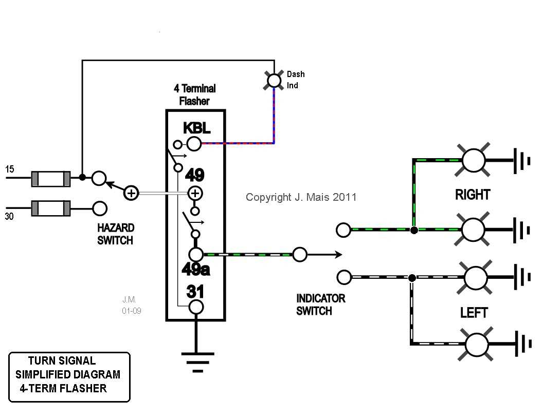
A signal light flasher wiring diagram is a diagram that shows the electrical connections and components involved in the operation of a signal light flasher. The signal light flasher is responsible for controlling the blinking of the turn signals or hazard lights in a vehicle. It is an essential component for indicating the intentions of the driver to other road users.
The wiring diagram typically includes information on the color coding of the wires, the connections to the vehicle’s electrical system, and the placement of the flasher unit. It may also indicate the use of additional components such as relays or resistors to ensure proper operation and compatibility with the vehicle’s electrical system.
Components:
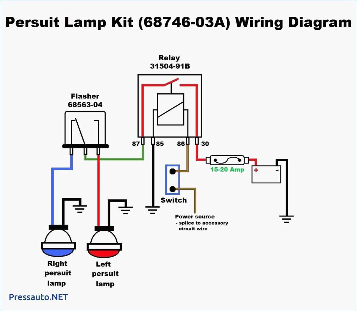
- Flasher unit: This is the main component responsible for controlling the sequence and speed of the turn signal or hazard light blinking. It is usually a small electronic device that can be plugged into a socket or connected directly to the vehicle’s wiring.
- Wiring harness: The wiring harness is a bundle of wires that connects the various electrical components in the vehicle. It typically includes connections for the signal lights, power source, and ground.
- Turn signal switch: The turn signal switch is a device located on the steering column or dashboard that allows the driver to activate the turn signals. It is usually a lever that can be positioned up or down to indicate the desired direction of turn.
- Indicator lights: The indicator lights are typically located on the vehicle’s exterior and provide a visual indication of the turn signal or hazard light activation. They are usually housed in lenses that are color-coded to indicate the intended direction of turn.
A properly wired signal light flasher is essential for the safe operation of a vehicle. Following the wiring diagram and ensuring correct connections will help ensure that the turn signals and hazard lights function correctly and communicate the driver’s intentions to other road users.
Understanding Signal Light Flashers
Signal light flashers are an important component in automotive electrical systems that control the flashing of turn signals and hazard lights. They provide the necessary circuitry to alternate the power supply to the bulbs, creating the flashing effect that alerts other drivers of your intended direction or emergency situation.
How do signal light flashers work?
Signal light flashers typically consist of a relay and a timing circuit. The relay is responsible for switching the power supply on and off to the bulbs, while the timing circuit controls the rate at which the power is alternated. The timing circuit can be either an electronic circuit or a bi-metallic strip, depending on the type of flasher.
Types of signal light flashers
There are two main types of signal light flashers: thermal flashers and electronic flashers. Thermal flashers use a bi-metallic strip that heats up and bends with the flow of electrical current. As the strip bends, it breaks the circuit, causing the lights to turn off. As the strip cools down, it straightens and completes the circuit again, turning the lights back on. This cycle of heating and cooling creates the flashing effect.
Electronic flashers, on the other hand, use an electronic timing circuit to control the flashing rate. These flashers are more precise and reliable than thermal flashers, as they are not affected by temperature variations. They can also be programmed to have different flashing patterns and rates.
How to wire a signal light flasher?
Wiring a signal light flasher involves connecting the flasher unit to the power source, turn signal switch, and the indicator lights. The flasher unit is usually installed near the steering column or in the fuse box. It is important to consult the wiring diagram specific to your vehicle to ensure proper installation.
Benefits of signal light flashers
Signal light flashers play a crucial role in promoting safety on the road. They enhance the visibility of your vehicle, especially during turns and emergency situations. Additionally, they allow other drivers to anticipate your movements and take appropriate actions to avoid accidents. Therefore, it is important to ensure that your signal light flashers are in proper working condition and properly wired.
Importance of a Wiring Diagram
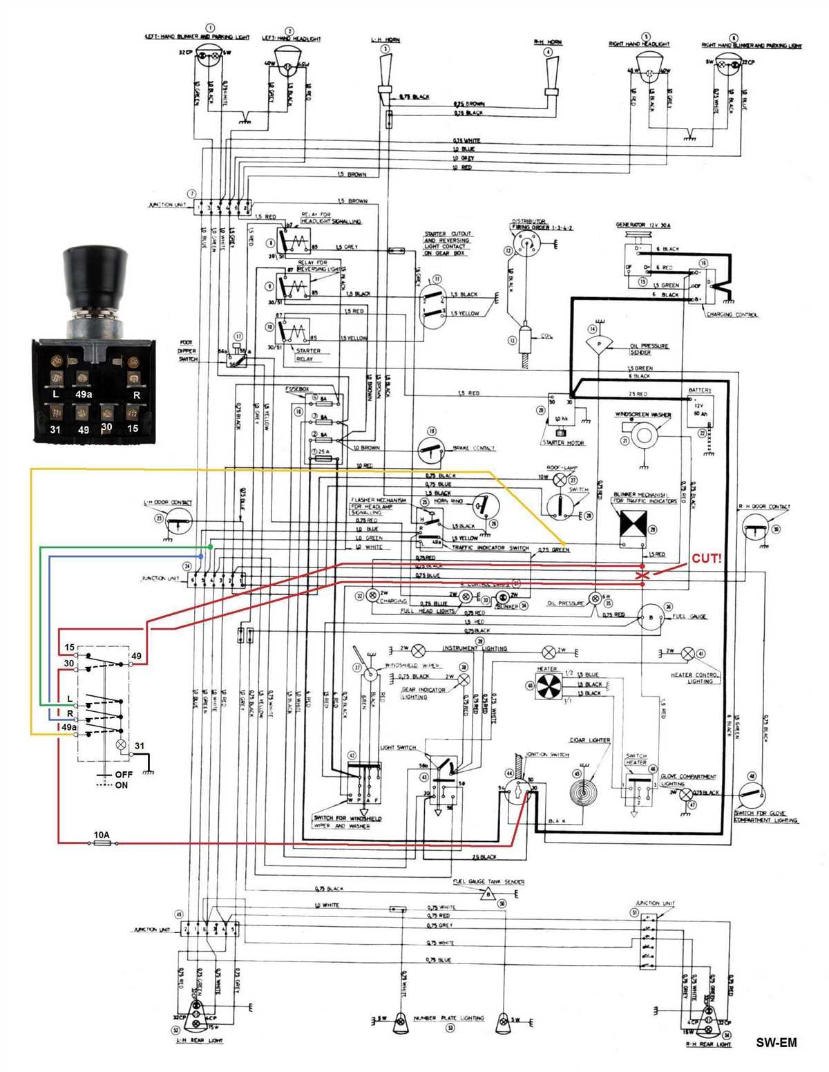
When it comes to working with electrical systems, having a clear and accurate wiring diagram is of utmost importance. A wiring diagram is a visual representation of the electrical circuitry in a particular system or device. It provides detailed information about the connections, components, and electrical codes that need to be followed during installation, maintenance, or troubleshooting.
A wiring diagram serves as a blueprint for electricians, technicians, and DIY enthusiasts, helping them understand how the system is set up and how the various components are interconnected. It allows them to identify the different wires, their color coding, and their function, making it easier to make accurate connections and avoid potential hazards.
With a wiring diagram, it becomes easier to trace the flow of electricity through the system and identify any faults or malfunctions. This is especially important when troubleshooting electrical issues, as it helps save time and effort by directing the technician to the specific areas or components that need attention.
Additionally, a wiring diagram also ensures compliance with electrical codes and standards. Every electrical installation must adhere to specific regulations to ensure safety and prevent accidents, such as fires or electric shocks. By following the wiring diagram, electricians can ensure that the system is installed correctly and in accordance with the necessary regulations.
In summary, a wiring diagram is an essential tool in the electrical field. It provides a visual representation of the circuitry, enables accurate connections, aids in troubleshooting, and ensures compliance with electrical codes. Whether you are working on a simple home electrical project or a complex industrial system, a wiring diagram is a valuable resource that shouldn’t be overlooked.
Steps to Wiring a Signal Light Flasher
Wiring a signal light flasher is an essential part of ensuring the proper functioning of your vehicle’s turn signals. Whether you are installing a new flasher or replacing an old one, following these steps will help you complete the process smoothly.
Gather the necessary materials
Before starting the wiring process, gather all the materials you will need, including a signal light flasher, electrical tape, wire strippers, and a wiring diagram specific to your vehicle’s make and model. Having all the necessary materials at hand will make the installation process much easier and faster.
Disconnect the battery
For safety reasons, it is essential to disconnect the vehicle’s battery before starting any wiring work. This will help prevent any electrical shocks or accidents during the installation process. Locate the battery in your vehicle and disconnect the negative terminal using a suitable wrench.
Refer to the wiring diagram
Consult the wiring diagram specific to your vehicle’s make and model to identify the wires that need to be connected to the signal light flasher. This diagram will provide you with the necessary information about the color-coded wires and their corresponding functions, making it easier to connect everything correctly.
Prepare the wires
Using wire strippers, carefully remove a small section of insulation from the ends of the wires that need to be connected to the signal light flasher. This will expose the bare wire, allowing for a secure and proper connection.
Connect the wires
Using the information from the wiring diagram, match the color-coded wires and connect them to the corresponding terminals on the signal light flasher. Ensure that the connections are secure and tight to prevent any loose connections that may lead to malfunctioning turn signals.
Test the signal light flasher
Once all the wires are connected, reconnect the negative terminal of the vehicle’s battery. Turn on the vehicle’s ignition and test the turn signals to ensure they are functioning correctly. If the signals are not working as expected, double-check the connections and consult the wiring diagram again to troubleshoot any potential issues.
Completing these steps will help you successfully wire a signal light flasher. It is important to take your time and follow the wiring diagram closely to ensure a proper and safe installation. If you are unsure about any step, it is always best to consult a professional or seek assistance from someone with experience in vehicle wiring.
Identifying Signal Light Flasher Wires
When working on signal light flasher wiring, it is important to understand how to identify the different wires involved. This knowledge is essential for troubleshooting, repair, or installation of signal light flashers.
Typically, there are three wires connected to a signal light flasher: the power wire, the ground wire, and the output wire. The power wire is responsible for providing the necessary electrical current to the flasher. It is usually connected to a power source, such as the vehicle’s battery or fuse box. The ground wire, on the other hand, completes the electrical circuit and is connected to the vehicle’s chassis or a designated ground point. Finally, the output wire delivers the flasher’s signal to the vehicle’s turn signal lights.
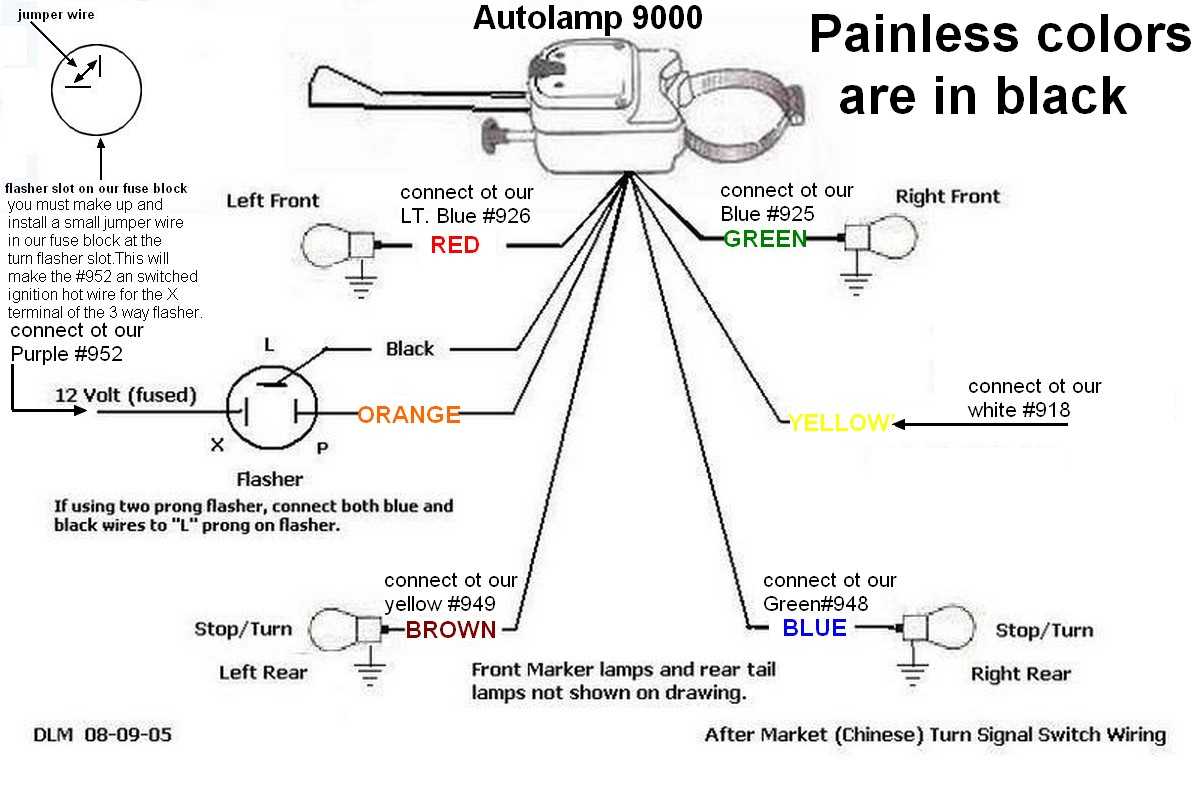
To identify these wires, it is helpful to consult the wiring diagram specific to the vehicle’s make and model. The diagram will outline the color-coding of the wires and their corresponding functions. Additionally, it is common for manufacturers to label the wires directly on the flasher unit itself.
When visually inspecting the wires, pay attention to their color and location. The power wire is often red, yellow, or orange and is connected to a positive terminal or a fuse box. The ground wire is typically black or brown and is secured to a metal component or chassis ground. The output wire can vary in color but is usually green, blue, or white, and it is connected to the turn signal lights.
Once the wires have been identified, it is important to test their connections using a multimeter or a test light. This will ensure that the wires are properly connected and that they are transmitting the correct electrical signals. If there are any issues, such as a faulty wire or a loose connection, they can be easily identified and resolved.
Connecting Signal Light Flasher Wires
When installing or repairing a signal light flasher, it is important to connect the wires correctly to ensure proper functioning of the system. The signal light flasher is responsible for controlling the flash rate of the turn signals in a vehicle, so it is essential to follow the wiring diagram provided for your specific flasher model.
Start by identifying the three wires coming from the signal light flasher unit. Usually, these wires are color-coded to indicate their purpose. The most common wire colors are black, yellow, and green. The black wire is typically the ground wire, while the yellow and green wires represent the left and right turn signals, respectively.
In most cases, the black wire should be connected to the vehicle’s grounded metal frame or chassis. This can usually be achieved by using a ring terminal to attach the wire securely to a bare metal surface. Ensure that the connection is tight to provide a good electrical ground.
The yellow and green wires should be connected to their respective turn signal wires in the vehicle’s wiring harness. This can be done by stripping a small section of insulation from the turn signal wires and splicing them together with the corresponding wires from the flasher unit. It is important to use wire connectors or solder these connections to ensure a secure and reliable connection.
Once all the connections are made, it is recommended to test the signal light flasher functionality before finalizing the installation. Turn on the vehicle’s ignition and activate the turn signals to check if they are flashing at the correct rate. If the flash rate is too fast or too slow, double-check the wiring connections and consult the wiring diagram for any potential errors.
Remember that accurate wiring is crucial for the proper operation of the signal light flasher system. Take your time to ensure each wire is connected correctly, and always consult the specific wiring diagram for your flasher model to avoid any potential issues.
Testing Signal Light Flasher Wiring
The signal light flasher wiring in a vehicle is responsible for controlling the flashing of the turn signal lights. If there is a problem with the wiring, it can cause the turn signals to malfunction or not work at all. To ensure that the signal light flasher wiring is functioning correctly, it’s important to test it.
Testing the Signal Light Flasher Wiring
Here are the steps to test the signal light flasher wiring:
- Check the fuse: Start by checking the fuse related to the turn signal lights. A blown fuse can cause the turn signals to stop working. Use a fuse tester or visually inspect the fuse to determine if it’s blown. If it is, replace it with a new one of the same amperage.
- Inspect the wiring connections: Check all the wiring connections related to the turn signal lights, including the flasher unit, turn signal switch, and bulbs. Ensure that the connections are secure and free from corrosion or damage. Repair or replace any faulty connections.
- Test the flasher unit: The flasher unit is responsible for controlling the flashing of the turn signal lights. Use a multimeter set to the continuity or resistance mode to test the flasher unit. Follow the manufacturer’s instructions to properly test the unit. If the unit is faulty, replace it with a new one.
- Check the turn signal switch: The turn signal switch is another component that can cause issues with the signal light flasher wiring. Test the switch by checking for continuity between the appropriate terminals when the switch is activated. If the switch is not functioning correctly, replace it.
- Test the bulbs: Finally, test the turn signal bulbs to ensure they are functioning correctly. Remove the bulbs and inspect them for any signs of damage or burned-out filaments. Test the bulbs using a bulb tester or by connecting them directly to a power source. Replace any faulty bulbs.
By following these steps, you can effectively test the signal light flasher wiring in your vehicle. If you encounter any issues that you’re unable to resolve, it may be necessary to consult a professional mechanic or automotive electrician for further assistance.
Q&A:
How can I test the signal light flasher wiring?
You can first check if the flasher relay is working properly by listening for a clicking sound when you activate the turn signal. If you don’t hear the clicking sound, the relay might need to be replaced. You can also use a multimeter to test the continuity of the wiring and look for any loose or damaged connections that can interfere with the operation of the signal lights.
What are the common issues with signal light flasher wiring?
Some common issues with signal light flasher wiring include loose or corroded connections, faulty flasher relay, damaged wiring, or a blown fuse. These issues can cause the signal lights to malfunction or not work at all. Regular maintenance and inspections can help prevent these issues and ensure the proper functioning of the signal lights.
How do I fix a faulty signal light flasher wiring?
If you suspect a fault in the signal light flasher wiring, you can start by inspecting the connections and wiring for any damage or looseness. If you find any issues, you can try tightening the connections or replacing damaged wiring. If the problem persists, you may need to replace the flasher relay or consult a professional for further diagnostics and repair.
Can I test the flasher relay without removing it?
Yes, you can test the flasher relay without removing it by listening for a clicking sound when you activate the turn signal. If you hear the clicking sound, it indicates that the relay is receiving the signal and is likely working properly. However, if you don’t hear any clicking sound, it might indicate a fault in the flasher relay, and you may need to replace it.
What should I do if my signal lights are not working even after testing the wiring?
If your signal lights are not working even after testing the wiring, there may be other issues at play. You can check the fuse for the signal lights and replace it if necessary. It is also possible that the turn signal switch or the bulbs are faulty and need to be replaced. If you are unable to troubleshoot the issue, it is best to consult a professional for further diagnosis and repair.
How can I test the signal light flasher wiring?
To test the signal light flasher wiring, you can use a digital multimeter. Start by disconnecting the flasher relay from the vehicle’s electrical system. Then, set the multimeter to the continuity testing mode. With the turn signal switch in the “off” position, check for continuity between the terminals of the flasher relay. There should be no continuity. Next, turn on the turn signal switch and check for continuity again. There should be continuity between the appropriate terminals depending on the direction of the turn signal. If there is continuity when the switch is off or no continuity when the switch is on, it indicates a wiring issue that needs to be addressed.