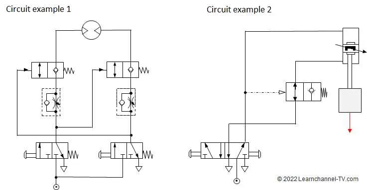
To ensure unidirectional flow and prevent backflow in compressed air networks, incorporate a specialized non-return device into your setup. This component is essential for maintaining system integrity and avoiding pressure drops caused by reverse motion.
Placement of this mechanism should be immediately downstream of the compressor or actuator to effectively block unwanted flow reversals. Proper installation reduces wear on equipment and enhances overall reliability.
When analyzing system layouts, focus on the schematic that outlines the arrangement of these directional flow controllers. Understanding the interplay between input and output ports within these devices allows for precise troubleshooting and optimization.
Selecting models with low cracking pressure and minimal leakage will improve efficiency. Additionally, integrating them with actuators that respond quickly to pressure changes ensures smooth operation under varying loads.
Flow Control Schematic for Air Systems
To ensure unidirectional airflow and prevent backflow in compressed air circuits, incorporate a non-return mechanism as shown below. This setup is essential for maintaining pressure stability and system integrity.
- Identify the input and output ports on the component that permits fluid passage in only one direction.
- Connect the source line to the inlet side, ensuring a tight seal to avoid leaks.
- Position the outlet towards the actuator or downstream equipment to maintain correct flow orientation.
- Include pressure gauges upstream and downstream to monitor system performance and detect flow irregularities.
Key considerations for effective operation:
- Material compatibility with working media to prevent corrosion and wear.
- Proper sizing to handle maximum expected flow rates without causing excessive pressure drops.
- Regular inspection points for cleaning or replacement to avoid clogging and system failure.
- Installation orientation aligned with the manufacturer’s specifications to guarantee proper functionality.
Implementing this schematic improves operational reliability by eliminating reverse flow, safeguarding compressors and other sensitive components from damage caused by flow reversal.
Interpreting Flow Direction and Symbol Meaning in Flow Control Schematics
Always identify the arrow indicators on the schematic to determine the intended fluid movement path. The arrow points toward the allowed passage direction, ensuring unidirectional flow and preventing backflow.
Recognize the graphical icon representing a directional control component: a triangle pointing toward a line or a bar. The triangle denotes the permitted flow route, while the line symbolizes the blocking mechanism when flow reversal occurs.
Note that the presence of a spring symbol adjacent to the flow path suggests automatic reset functionality, maintaining closure when pressure reverses. This prevents unwanted fluid return and maintains system integrity.
When analyzing the schematic, confirm that the component is oriented according to the indicated flow direction, matching the triangle’s point with the system’s flow stream. Misalignment may cause operational failure.
In complex layouts, locate supplementary symbols such as pressure or flow regulators linked to the component to understand interaction within the network and confirm proper sequencing of flow control elements.
Identifying Common Configurations in Air Flow Control Circuits
Focus on locating the most used arrangements that prevent reverse airflow and maintain directional control. The typical designs include the spring-loaded one-way mechanism, which uses a spring to close the passage when flow reverses, ensuring reliable sealing under variable pressures.
Another widespread format involves a flap or disk that shifts only when air moves forward, blocking backward movement by seating firmly against the flow path. This type is favored for its simplicity and low pressure drop.
For higher pressure systems, the piston-style arrangement provides enhanced durability and tight shutoff, using a cylindrical element that slides within a bore to stop flow reversal effectively.
Additionally, consider the use of ball-based configurations, where a spherical component moves to seal the passage, offering quick response and minimal leakage, especially in compact setups.
When analyzing circuit layouts, identify symbols representing these directional flow restrictors by noting elements that only allow fluid transit in one direction, often depicted as arrows with blocking devices oriented accordingly.
In summary, recognizing these fundamental patterns enables accurate troubleshooting and optimization of compressed air distribution systems by ensuring proper flow orientation and preventing contamination or damage due to backflow.
Troubleshooting Pressure Drop and Backflow Issues Using System Schematics
When facing pressure drops or backflow in your air-driven systems, start by identifying any possible blockages or restrictions in airflow. Review the system layout to locate components where flow is likely to be interrupted, such as filters, regulators, or fittings. Check for any signs of wear or buildup in these areas that could impede the movement of air.
Inspect connections and seals for leaks. Leaks can lead to unwanted pressure loss and backflow, especially around junctions and tightening points. Tighten any loose fittings and replace damaged seals to restore proper system pressure.
Ensure that all directional components are functioning as intended. A malfunction in a component designed to control flow direction can result in improper pressure regulation and cause reverse airflow. Double-check the flow orientation in the system layout for accuracy.
Verify that the control mechanism, such as pressure regulators or restrictors, is calibrated correctly. If a regulator is set too low or too high, it can lead to irregular pressure, causing either a drop in the system’s efficiency or backflow. Adjust or replace any miscalibrated devices based on the specifications provided by the manufacturer.
Finally, confirm that there are no obstructions in the exhaust or discharge ports. Blockages in these areas can prevent the system from releasing pressure, creating backflow conditions that compromise performance. Regularly clean and inspect these exits to maintain optimal function.