For anyone working on the electrical system of an E90 model with the N51 engine, understanding the wiring connections to the engine control unit (ECU) is crucial for diagnostics and repairs. The key to effective troubleshooting lies in knowing how power and data flow to and from critical components like the fuel injectors, ignition coils, and sensors.
Focus on identifying the precise pin-out configuration of the ECU connectors. Pinouts for the DME (Digital Motor Electronics) unit are essential when performing repairs or replacements. Ensure to check the grounding points as well, as improper connections can cause erratic behavior in engine performance or complete failure of the system.
When tackling faults, always verify the continuity and signal integrity for all major inputs, including the throttle position sensor, camshaft and crankshaft sensors. These inputs play a vital role in engine timing and performance. Without correct information from these sensors, the ECU will not be able to make proper adjustments to fuel delivery or ignition timing.
For accurate and efficient troubleshooting, ensure you have the proper circuit testing tools. Use a multimeter to check for voltage irregularities, and remember that a good understanding of the system layout will help avoid unnecessary disassemblies.
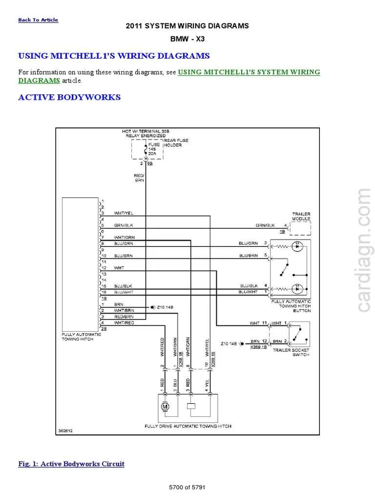
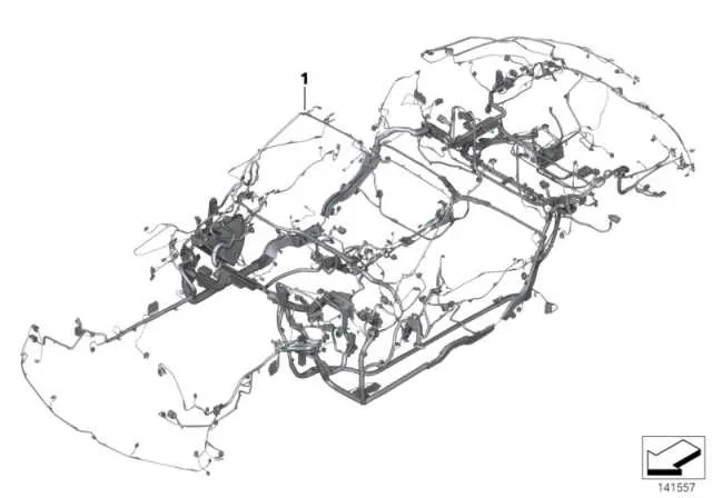
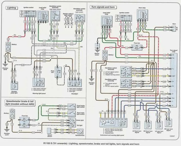
Pro tip: It’s highly recommended to use a detailed electrical schematic specific to this model for reference. This helps in pinpointing faulty wiring or components faster, ensuring minimal downtime.
Engine Control Unit Electrical Connections

Ensure all power connections to the ECU are secure. The primary power supply is typically routed through the main fuse box. Check for any corrosion or loose connections at the power terminals to avoid voltage instability that could affect performance.
Verify the ground connections. Poor grounding can result in erratic engine behavior, including misfires or difficulty starting. Ground wires should be tight and free of corrosion. Clean the contact points where the ground wires connect to the engine block or chassis.
Examine the sensor wiring, particularly for the camshaft and crankshaft sensors. These sensors are critical for proper timing and synchronization. Damaged or frayed wires can lead to inaccurate readings, causing engine performance issues or failure to start.
Inspect the connections to the fuel injectors and ignition coils. These components are directly influenced by the ECU’s signals. Loose or faulty connectors could result in uneven fuel distribution or misfires. Make sure connectors are properly seated and that wires are not subject to excessive heat or wear.
| Component | Connection Type | Inspection Tips |
|---|---|---|
| Power Supply | Positive Terminal | Ensure secure connection, no corrosion, and proper voltage. |
| Ground Connection | Chassis/Engine Ground | Check for clean, tight, and corrosion-free contact. |
| Camshaft Sensor | Two-Wire Connector | Check for damaged wires or loose connections. |
| Crankshaft Sensor | Two-Wire Connector | Ensure wires are not worn or damaged. |
| Fuel Injectors | Four-Wire Connector | Inspect connectors for tightness and no signs of wear. |
| Ignition Coils | Four-Wire Connector | Confirm secure connection, no corrosion, or wear. |
Regularly inspect the ECU for any signs of overheating. The ECU is usually mounted near heat sources and should be insulated to prevent temperature-related malfunctions. If overheating is suspected, check the cooling system for blockages or leaks.
Ensure all connectors are free of moisture. Water intrusion can cause shorts or corrosion, leading to erratic engine behavior. Apply dielectric grease to all connectors to prevent moisture from entering and to enhance conductivity.
Understanding the Power Supply Connections in the ECU Circuitry
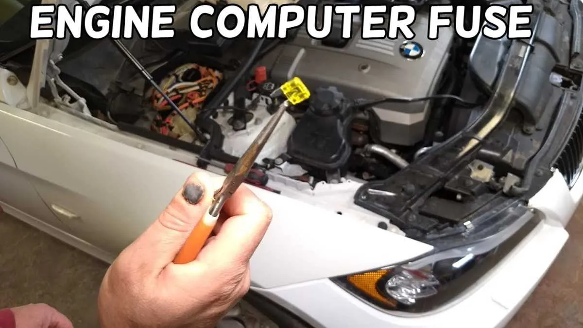
Ensure the main power feed to the ECU is stable by verifying the connection to the fuse box. The ECU requires a constant 12V supply to operate correctly. This voltage is typically routed through a dedicated fuse, which should be checked for continuity and proper amperage ratings.
In addition to the constant supply, the ECU also requires a switched 12V source to activate its internal components when the ignition is turned on. This power feed often originates from the ignition relay, which should be checked for signs of wear or malfunction.
The ground connections are equally crucial. The ECU must be properly grounded to prevent electrical interference and ensure accurate operation. Inspect the ground wires connected to the ECU, making sure they are free of corrosion and securely attached to the vehicle’s chassis.
Check for any power supply disruptions caused by damaged or loose connections in the power or ground circuits. This can lead to erratic ECU behavior, poor engine performance, or even a complete failure to start. Always use a multimeter to verify voltage levels at the ECU’s power inputs.
Ensure that the power feed to the ECU is not shared with other critical systems, as voltage drops caused by multiple power demands can lead to ECU malfunctions. If necessary, use a dedicated power line directly from the fuse panel to avoid overloading.
Locating and Troubleshooting Faulty Ground Connections in the ECU Circuit

Start by identifying the ground points that provide a return path for current in the ECU system. These are usually located on the engine block, chassis, or near the battery. Pay close attention to connections where the wires meet metal surfaces, as corrosion or looseness can cause electrical issues.
To find faulty grounds, check for any voltage drop across the ground connections. Use a multimeter to measure continuity from the ECU ground pin to the chassis ground. Any significant resistance indicates a problem with the connection. Clean all ground points to ensure there is no corrosion or dirt interrupting the circuit.
If the engine management system is experiencing erratic behavior or poor performance, inspect all ground wires for signs of wear or damage. Ground wires can degrade over time due to engine heat, vibrations, or exposure to chemicals. Replace damaged wires with ones that match the original specifications to maintain a solid connection.
During troubleshooting, always ensure the ECU is properly grounded before making any adjustments or measurements. Use the vehicle’s service manual to confirm the exact location of each ground point and ensure all connections are secure.
Interpreting the Pinout for the 3-Series ECU Module

Understanding the pinout of the ECU in a 3-Series car is crucial for diagnosing electrical issues and ensuring proper component connections. Start by identifying each pin’s function before making any modifications or repairs. Here’s how to approach it:
- Pin 1: Typically used for the ground connection. Ensure the integrity of the ground wiring for stable ECU performance.
- Pin 2: This is usually the ignition signal. Verify that the ignition is reaching the ECU for correct startup behavior.
- Pin 3: Often linked to the fuel injector circuit. Inspect this pin for corrosion or damage, as it directly affects fuel delivery.
- Pin 4: Can be a sensor input for engine temperature. Test for voltage fluctuations, as improper readings may indicate faulty sensors.
- Pin 5: Control for the ignition coil. Ensure solid connections to prevent misfiring or engine performance loss.
Next, pay attention to the following when working with the ECU pinout:
- Wire Colors: Cross-check each wire color with the vehicle’s manual to avoid miswiring. For example, a red wire might signal power, while a black one indicates ground.
- Pin Orientation: Make sure the connector is aligned correctly with the pinout before inserting or removing wiring to avoid bent pins or incorrect connections.
- Voltage Readings: Use a multimeter to test voltage on each pin. Deviations from expected values can indicate issues with wiring or related components.
Carefully map out the pin functions for diagnostic or repair work, and always double-check connections to ensure proper electrical flow.