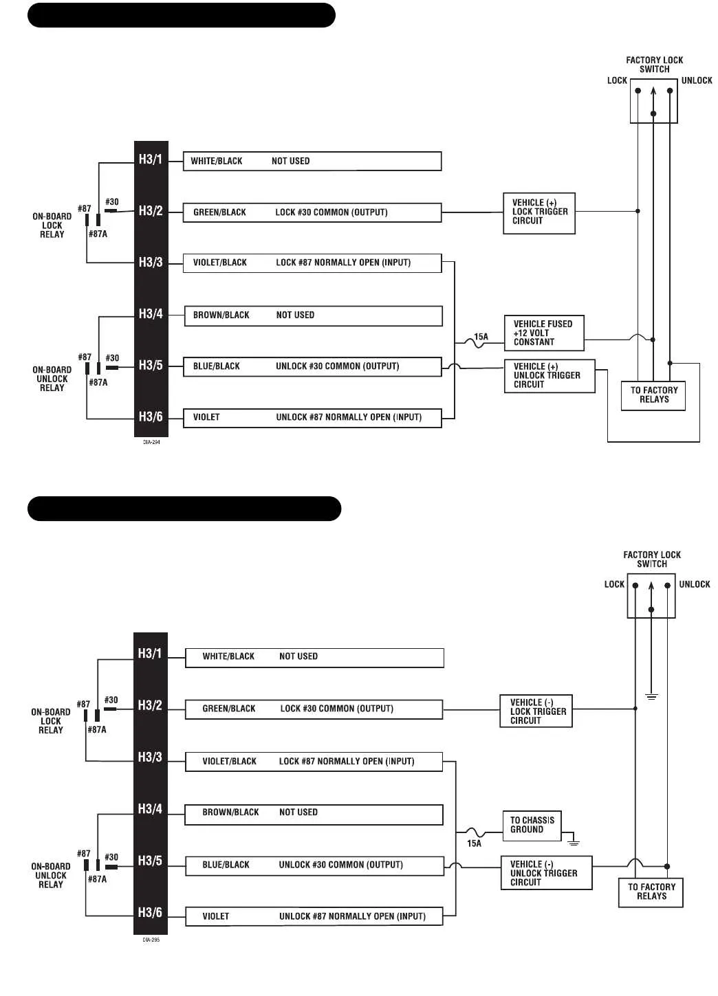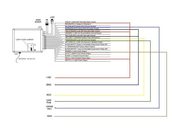
For a smooth installation process of your vehicle’s security system, it’s crucial to understand the exact connections required for various components. Start by locating the main control unit, which serves as the hub for all electronic connections. From here, you will need to properly connect the power, ground, and accessory wires, ensuring a stable connection for proper system functionality.
Next, focus on integrating the sensors and triggers. These devices, which include door and motion sensors, must be wired into the correct zones to ensure they react accurately to changes in the environment. Always double-check the sensor’s polarity and the correct input/output terminals for seamless performance.
For an added layer of protection, consider linking the system with the vehicle’s ignition circuit. This will prevent unauthorized starting of the engine when the security system is engaged. Pay attention to the ignition switch wiring and confirm that the system correctly interacts with the vehicle’s electrical architecture to avoid accidental lockouts or malfunctions.
Tip: Always refer to the system’s manual for any model-specific wiring instructions to avoid potential hazards and ensure proper integration with your car’s existing electrical setup. Having a well-planned layout can significantly reduce troubleshooting time and improve the overall reliability of the setup.
Wiring Guide for Vehicle Security Systems

Ensure proper connection to the power source by locating the 12V constant and accessory wires in the vehicle. The constant power should be routed to the main unit, while the accessory line connects to the ignition or the key switch. This step is critical for enabling the system to arm and disarm in synchronization with the car’s ignition.
Door trigger connections are essential for detecting the opening of any entry point. Typically, the switch circuit from each door should be spliced into the main unit. This setup will activate the response mechanism when a door is opened while the system is armed.
Grounding is another key element. Ensure that the ground wire from the control unit is connected to a clean metal surface on the vehicle chassis. This will allow the system to operate without interference or erratic behavior due to poor ground connections.
Starter interrupt feature can be added to prevent unauthorized engine starts. This function requires a relay installation between the starter motor and ignition circuit, ensuring that if the system is triggered, it will disable the ignition or starter circuit.
Shock and motion sensors should be connected to the system’s auxiliary input. The proper calibration of these sensors is necessary to ensure they trigger accurately in response to impacts or movement around the vehicle, preventing false alerts.
Testing each zone during installation is a must. After wiring the system, check each circuit for continuity and confirm that the response actions (like sirens or lights) are activated as intended. Regular testing ensures the system operates at its full capacity and remains reliable.
Connect to additional security features like a GPS tracking system or a two-way communication module to enhance vehicle protection. These features should be integrated with the main control unit, ensuring seamless operation and remote control over the system’s status.
How to Connect the Main Control Unit to the Vehicle’s Power Supply
Begin by identifying the vehicle’s battery and the main power leads from the control unit. The red wire is typically used for the positive connection, while the black wire is for the negative. Ensure the power is off before proceeding with any wiring to avoid short circuits.
Locate the fuse box in your vehicle and identify a reliable power source that provides a constant 12V signal. This is usually a larger wire, often red or yellow, that connects directly to the battery. Attach the red wire from the control unit to this constant 12V source.
For the ground connection, find a solid metal surface on the vehicle’s frame or chassis. This ensures a stable connection. The black wire from the control unit should be attached to this metal surface using a self-tapping screw or an appropriate grounding bolt.
After securing the power and ground wires, double-check the connections for any possible loose or weak points. It is important that these connections are firm and insulated to prevent accidental disconnections or shorting.
Test the system by turning the vehicle on and checking the power to the control unit. If there is no response, recheck your connections to ensure everything is wired correctly.
Identifying and Connecting the Key Components in the Security System
Start by identifying the key elements of your system, including the main control unit, sensors, siren, and power supply. Each component has a specific role in the setup, and proper connections are critical for smooth operation.
- Main Control Unit: Typically located under the dashboard, this is the brain of the system. It connects to every other component, managing their inputs and outputs. Ensure solid power connections and proper ground placement.
- Sensors: Install door, window, and motion sensors to the designated inputs on the control unit. Use the correct pins for each sensor type, following the manufacturer’s color code for wires.
- Power Supply: The system requires a constant 12V DC source. Connect the power wire to the vehicle’s battery terminal, and use an inline fuse to protect against short circuits. Be mindful of the battery’s polarity.
- Siren: This component produces the audible alert. Connect it to the siren output terminal on the control unit, ensuring the wire is tightly secured to avoid disconnections.
Verify all connections before powering on the system. Test each sensor to ensure proper triggering, and check that the siren functions as expected. Properly securing each wire with cable ties will prevent movement that could lead to wear or malfunction.
Finally, test the entire system by arming and disarming it, checking all sensors, and confirming that the sound system activates during an alert.
Troubleshooting Common Electrical Issues in Security System Installations
If the system fails to activate, start by checking the connection to the vehicle’s power source. A loose or poorly connected wire at the battery terminal can prevent the unit from receiving sufficient power. Ensure that all connections are tight and clean, and use a multimeter to check for voltage across key points in the setup.
For systems not responding to remote signals, examine the antenna wire connection. If the antenna is not properly installed or if there is a break in the connection, the system will struggle to receive signals. Additionally, verify that the antenna is unobstructed and located in a position with minimal interference from metal components.
In cases where the system goes off unexpectedly, it may be due to a grounding issue. Check for improper ground connections, especially in areas where metal parts of the vehicle are involved. An unreliable ground can cause erratic behavior or false triggering. The ground wire should be securely attached to a clean, rust-free metal surface.
When the system fails to trigger upon entry or exit, confirm that all door switches are wired correctly. A malfunction in the door input switch or a faulty connection can prevent the system from detecting door activity. Use continuity testing to ensure proper flow in each switch circuit.
If the system’s siren fails to sound, inspect the connection to the siren itself. A damaged or corroded connection may prevent the device from receiving signals. Additionally, check the siren fuse to ensure it has not blown. Replace fuses only with those of the correct amperage to avoid further issues.
For non-responsive sensors, inspect the wiring and connectors leading to the sensor module. Loose connections or frayed wires can cause intermittent or total failure. Ensure each wire is securely connected and free of damage, particularly at the sensor terminals.
Lastly, when all else fails, double-check the entire installation for shorts or misrouted cables. Any misplaced wire could cause a system failure. Use a wire tracker tool to identify shorts or misconnections, and reroute wires as necessary to avoid electrical interference.