When setting up an industrial electric machine for optimal performance, always ensure that the wires are configured in the most efficient way for power distribution. The configuration involving three separate conductors ensures smooth operation and helps balance the load across each line. Each conductor should be connected properly to avoid imbalances that can lead to overheating or premature wear of equipment.
Ensure that you adhere to the correct sequence of leads, typically marked as L1, L2, and L3, when hooking up the machine to the power source. The terminals for the device should be clearly labeled, and it’s crucial that they correspond correctly with the incoming lines from the power supply. Incorrect matching can result in reverse rotation or excessive strain on the internal components.
Key tip: Always double-check the terminal connections and the type of wiring used. In some configurations, a star or delta arrangement may be employed, where specific wiring techniques allow for either reduced voltage or full-load operation depending on your needs. This flexibility in setup can help in optimizing the energy consumption and performance, depending on the situation.
Remember to use the appropriate gauge wire that suits the voltage and current requirements to prevent electrical hazards and ensure the reliability of the setup. A detailed understanding of the setup and thorough checking of all components will help prolong the lifespan of the machinery and ensure efficiency.
Wiring Layout for a 3-Phase Electrical Device

Ensure correct alignment of the leads: the power supply should have three conductors, each carrying alternating current. Label them as L1, L2, and L3 for clarity. Properly connect these to the terminals of the apparatus, maintaining the designated order of the phases to avoid reverse rotation.
The neutral wire, when used, should connect to the common terminal of the device. It’s important to note that this component typically balances the system but is not always necessary for certain configurations where only the live wires are used for operation.
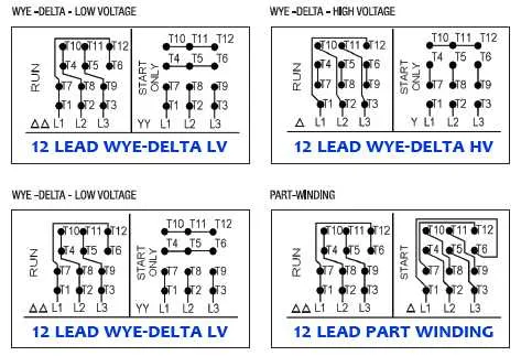
When setting up a star or delta configuration, be mindful of the specific setup requirements. In a star layout, each winding is linked to a central point, while in a delta arrangement, the ends of the windings are connected together to form a loop.
Verify all connections with a multimeter before powering up to confirm there is no short circuit or open circuit. Make sure to inspect the voltage ratings and match them to the specifications of the equipment to avoid overloading and potential damage.
Double-check that all terminals are securely fastened to prevent loose connections, which could lead to overheating or failure during operation. Use proper insulation for the wires and ensure there is no exposed copper to prevent short circuits and electric shock hazards.
Understanding the Wiring Configuration for Star and Delta Arrangements
For optimal performance, it’s essential to choose between Star and Delta setups based on voltage and current needs.
- Star Configuration: In this arrangement, each winding is connected to a common point, forming a “Y” shape. This reduces voltage across each coil, providing a lower starting torque and less stress on the system. It’s suitable for low-voltage applications.
- Delta Configuration: In the Delta wiring, each winding connects to the other, creating a closed loop. This configuration provides higher torque and is ideal for high-voltage scenarios where maximum power output is needed.
Key Differences:
- Voltage Handling: The Star connection is better for lower voltage systems, while Delta supports higher voltage operation.
- Current Requirements: In Star, the current through each winding is lower, making it more efficient for reduced-load operations. Delta requires higher current but can handle more significant power output.
- Torque Output: The Delta setup offers higher torque compared to Star, which is more suitable for heavy-duty applications.
Switching Between Configurations:
- Identify the required voltage and current values based on the equipment’s rating.
- For starting with lower torque, use the Star configuration and switch to Delta once stable operation is achieved.
- Ensure proper wiring is done for each setup to avoid overloads and ensure system stability.
Choosing the right configuration directly impacts performance, efficiency, and the overall reliability of the setup.
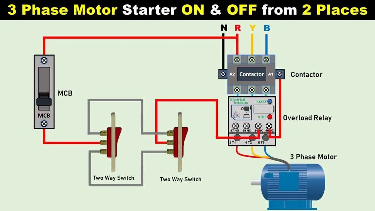
How to Connect a Three-Phase Motor to a Starter: A Step-by-Step Guide
Ensure power is off at the main breaker before starting any wiring work. Lockout/tagout procedures must be followed to prevent accidental energizing.
Identify terminals on the starter: L1, L2, L3 for incoming supply and T1, T2, T3 for output to the rotating device. Use a multimeter to verify no voltage is present.
Connect supply lines from the distribution panel to L1, L2, and L3. Use appropriately rated cable, typically 10 AWG or larger, depending on current load and run length.
Attach output leads from T1, T2, and T3 to the winding inputs of the rotating equipment. Follow the manufacturer’s terminal markings, often U, V, W.
Wire the control circuit to include an overload relay between T-terminals and the output load. Connect the start and stop push-buttons in series with the coil input (usually marked A1 and A2).
Test the rotation direction after energizing. If the shaft spins in reverse, power off and swap any two output conductors at the starter’s T-terminals.
Secure all connections with proper torque as specified by the terminal blocks. Recheck every screw for tightness to avoid arcing or overheating under load.
Troubleshooting Common Issues in Industrial Drive Wiring

Immediately check voltage symmetry at all terminals using a calibrated multimeter; deviations above 5% between lines indicate imbalance, which can overheat windings and cause insulation failure.
Inspect terminal lugs for oxidation or looseness–arcing signs such as discoloration or pitting require terminal replacement and proper torque application per IEC 60204-1.
Use an insulation resistance tester (1,000V scale) to verify minimum 1 MΩ between each lead and earth. Readings below this indicate moisture or insulation breakdown; dry the unit and re-test.
Verify rotation sequence with a phase tester. If rotation is reversed, interchange any two supply lines–never change internal winding leads unless rewiring.
Inspect overload relays for trip calibration. Set current limit to 115% of full load rating for standard duty cycles. For frequent starts, reduce to 105% and monitor trip frequency.
Measure start-up current with a clamp meter. Readings exceeding 600% of nameplate amperage suggest wiring faults, shorted windings, or mechanical obstruction. Disconnect load and retest stator leads individually.
Check contactor points for wear or welds. Excessive arcing during energization can lock contacts closed, bypassing overload protection. Replace contactor and test control logic before restart.