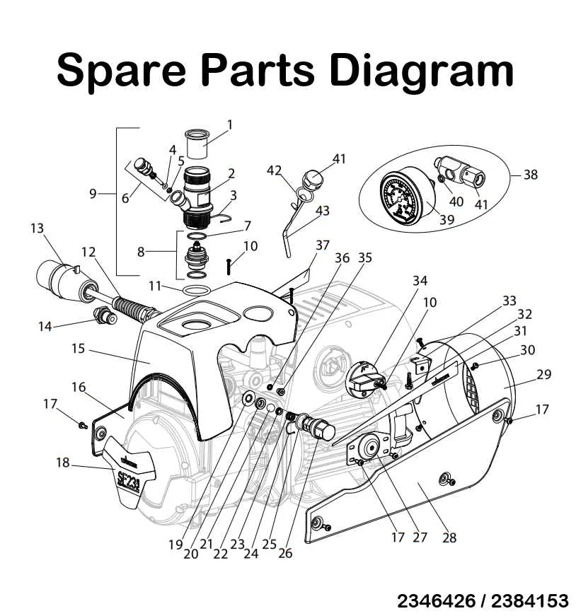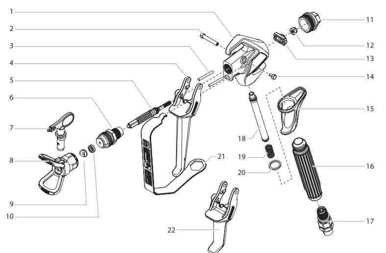
When maintaining or repairing your spray equipment, it’s crucial to have a clear understanding of its components. Knowing how each part interacts ensures effective troubleshooting and smooth operation. Start by identifying the core elements, such as the pump, nozzle, and hose. These are key to the device’s performance and require regular inspection for wear and tear.
Check for wear on seals and gaskets, as they play a significant role in maintaining pressure and preventing leaks. Over time, these elements can degrade, causing reduced performance or even malfunction. Replace any worn components to keep your system running smoothly.
Proper assembly is just as important as regular maintenance. Make sure all parts are correctly aligned and tightened. Misalignment can lead to inefficient spraying or even damage the unit. Consult a detailed illustration or manual specific to your model to ensure all components are in the right place.
For a comprehensive repair, always use genuine parts. Using non-original replacements can lead to compatibility issues and potential damage to your equipment. Familiarize yourself with part numbers and their specific functions to avoid costly mistakes.
Key Components Breakdown
For optimal maintenance, it’s essential to understand the key elements of your spray equipment. Below is a detailed breakdown of the main parts and their functions.
- Spray Gun: The central tool for applying coatings, with a nozzle that controls the spray pattern. Ensure it’s cleaned regularly to prevent clogging.
- Pressure Regulator: A critical part to manage the flow of material. Adjust to the required pressure to ensure uniform application.
- Fluid Hose: Connects the spray gun to the tank, transferring the coating material. Inspect regularly for leaks and wear.
- Material Tank: Holds the liquid to be sprayed. Check the capacity and clean it after each use to avoid buildup.
- Air Filter: Protects the internal components from dirt and debris. Replace periodically to maintain air quality and performance.
These components work together to provide precise, smooth coating applications. Routine maintenance and prompt replacement of worn-out parts will extend the lifespan of the equipment and maintain top performance.
How to Identify and Replace Key Components of the Wagner Pro 130
Start by disconnecting the power and relieving system pressure. This prevents accidental discharge during disassembly. Use a flathead screwdriver to remove the housing cover, revealing the internal layout.
Inspect the inlet valve first. It’s located near the suction tube. If clogged or stuck, remove it using needle-nose pliers and install a replacement with the same O-ring size (typically 5/16″ ID).
Check the piston assembly next. A worn piston often causes pulsating flow or pressure loss. Unscrew the pump housing with a 7/8″ socket, extract the piston, and examine the seals. If damaged, swap the piston and install new seals from a rebuild kit labeled for 0.015–0.017 tip sizes.
Examine the return valve. Found beneath the fluid section, it regulates flow when the trigger is released. If paint leaks from the return line, replace the spring and ball assembly using a hex wrench.
Look at the filter inside the spray handle. Unscrew the gun’s base, slide out the mesh insert, and replace if it shows embedded debris or deformation. Use fine mesh (60–100 mesh) for latex or medium coatings.
Finish by testing the unit with clean water. Check for consistent spray pattern and no leaks. Tighten all connections using torque specs provided in the maintenance sheet (typically 15–20 in-lbs for fittings).
Common Issues with Wagner Pro 130 Parts and How to Troubleshoot Them
Clogged spray tip: Remove the nozzle and clean it with warm water and a soft brush. If buildup persists, soak in a compatible cleaning solution for 30 minutes. Never use metal tools that could distort the orifice.
Loss of pressure: Check the inlet valve for debris. If the suction tube is not fully submerged or has cracks, replace it. Examine the piston assembly for wear–if pitting or scoring is visible, install a new kit.
Motor runs but no material dispenses: Inspect the prime/spray valve. If it’s stuck or leaking, clean or swap it out. Ensure the intake filter isn’t blocked. Replace if mesh is torn or discolored.
Pulsing spray pattern: This often results from a worn-out seal or damaged packing. Disassemble the fluid section, inspect each gasket, and install replacements if rubber is deformed or swollen.
Unit won’t start: Confirm that the power cord is intact and properly connected. Use a multimeter to check the trigger switch and control board. If no continuity is detected, replace the faulty component.
Step-by-Step Guide to Assembling from the Technical Schematic

Begin by aligning the motor housing with the base unit. Secure using the four T25 screws, tightening diagonally to ensure even pressure distribution. Do not overtighten to avoid cracking the plastic casing.
Next, insert the piston assembly into the cylinder bore. Lubricate the piston with a light layer of silicone grease to reduce wear during initial operation. Rotate slightly while inserting to seat it fully.
Attach the inlet valve by pressing it into the lower chamber until it clicks into place. Ensure the O-ring is properly seated to prevent suction loss. Connect the suction tube and verify the clamp is tight.
Mount the outlet fitting to the top of the fluid section using a 17mm wrench. Align the outlet hose with the connector and twist clockwise until hand-tight, then apply an additional quarter-turn with pliers.
Secure the spray hose to the trigger assembly. Confirm that the filter screen inside the handle is clean and seated correctly. Insert the tip guard and twist until it locks. Test the trigger to confirm smooth operation.
Finally, verify all fasteners are secure. Check for alignment by referencing the schematic grid, ensuring each labeled component is in its designated quadrant. Run a brief priming cycle with water to check for leaks.