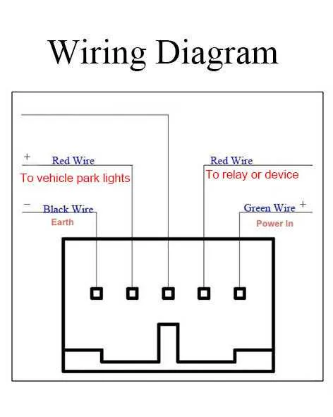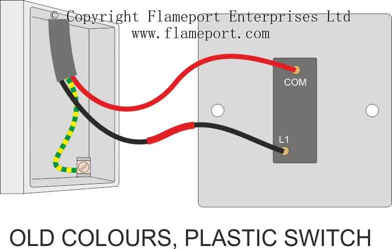
For reliable operation of your electrical toggles, always start by identifying the line (hot) and load conductors before making any connections. Confirm that the power is off using a non-contact voltage tester to prevent accidents.
Use a color-coded approach: black or red wires typically serve as live feed, while white wires are neutral and green or bare copper act as grounding paths. Ensuring correct polarity prevents malfunction and potential hazards.
When configuring single-pole or multi-location toggles, carefully route traveler wires and verify all junction points with a continuity tester. Avoid daisy-chaining terminals that aren’t designed for multiple connections to maintain circuit integrity.
How to Connect a Single-Pole Toggle Step-by-Step
Turn off power at the circuit breaker before starting any electrical work to prevent hazards.
Use a voltage tester to confirm the absence of current on the wires you will handle.
Identify the two black conductors: one is the incoming live feed, the other leads to the fixture.
Connect these conductors to the two brass-colored terminals on the device. Polarity does not matter for this simple on/off control.
Attach the bare or green grounding conductor to the green screw or grounding terminal on the metal frame.
Ensure all connections are tight to avoid arcing and overheating.
Carefully push the connected device into the electrical box without dislodging any wires.
Secure the plate and restore power at the breaker panel.
Test functionality by toggling the control to confirm proper operation of the circuit.
Connecting a Three-Way Mechanism for Controlling Illumination from Two Points
Use two special toggles designed for multi-location control, connected via a pair of traveler conductors. Start by identifying the line feed and load conductors: one connects to the common terminal on the first device, the other to the common on the second. Between these two toggles, run two insulated conductors (travelers) attached to the traveler terminals on both ends.
Ensure the neutral conductor bypasses the toggles and connects directly to the fixture’s neutral terminal. Grounding must be continuous through the metal boxes and devices for safety compliance. Use cable rated for at least 14 AWG for a 15-amp circuit or 12 AWG for a 20-amp circuit.
Label traveler wires to avoid confusion during installation. Verify that the common terminal on each unit is correctly identified – it’s usually marked differently or colored black. Test continuity before finalizing connections to confirm proper circuit behavior.
Connecting a Smart Control Device to Existing Electrical Infrastructure

Ensure power is completely shut off at the breaker panel before starting installation. Identify the line (hot) conductor, which supplies constant voltage, and the load conductor going to the fixture. Most conventional setups include a neutral wire, which is essential for modern automated units; verify its presence in the wall box. If the neutral is missing, consult local electrical codes or consider alternative devices designed for no-neutral applications.
Use a voltage tester to confirm wire functions. Connect the device’s line terminal to the home’s live conductor, and the load terminal to the outgoing conductor leading to the fixture. Attach the neutral terminal to the bundle of neutral conductors in the box, typically white wires twisted together. Ground the unit by securing the green or bare copper wire to the grounding screw or grounding conductor.
For multi-location control setups, include traveler wires as specified by the device manufacturer. Employ wire nuts rated for the gauge and number of conductors to ensure secure connections. Avoid splicing different wire gauges or mixing aluminum with copper unless proper connectors are used. After connections, carefully fold the wires into the enclosure to prevent strain or pinching.
Restore power and test the unit’s operation via manual toggling and app control, if applicable. Confirm the device responds correctly to commands and that no flickering or buzzing occurs. If any irregularities arise, recheck all connections and verify compatibility with the home’s electrical configuration.