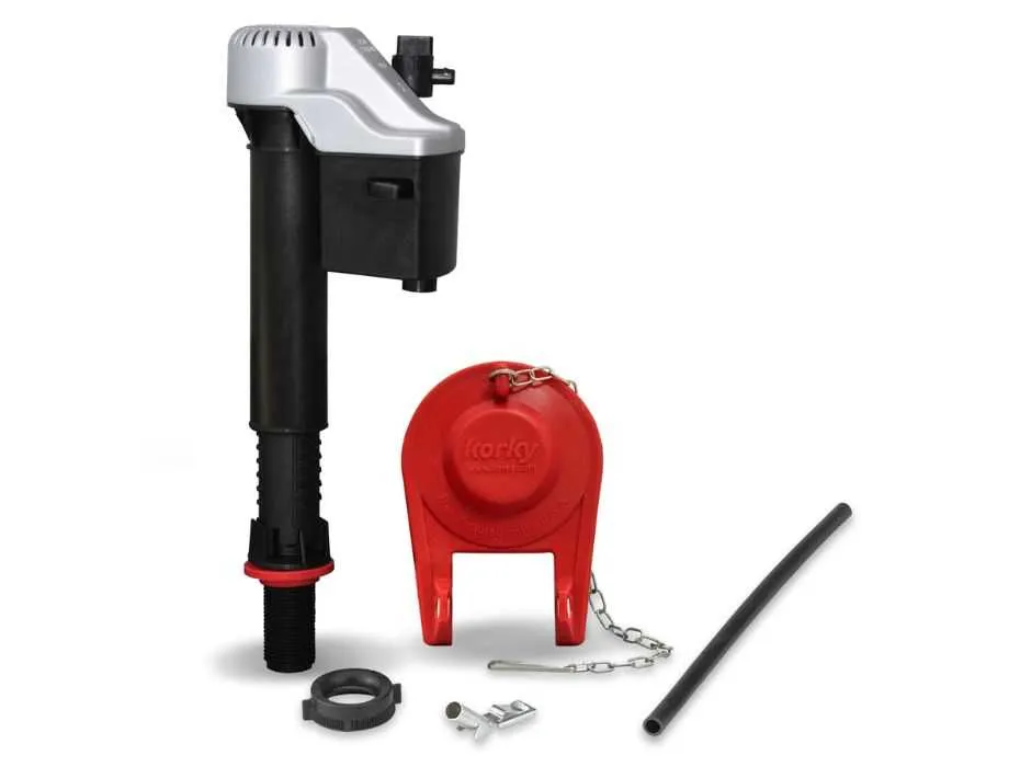
Replace the flapper mechanism every 18 months to prevent silent leaks under normal usage. A high-quality rubber seal rated for 100,000 cycles ensures optimal closure pressure. Check the sliding rod alignment after each replacement to maintain a consistent water level at 1 inch below the overflow tube.
Adjust the fill assembly so the float arm sits at exactly 7 inches from the base of the fill chamber for proper refill volume. If your refill speed drops below 20 seconds per gallon, clean the inlet screen and verify the plastic valve seat shows no signs of mineral buildup. Use a 1/4-inch wrench at 15 in-lb torque to secure the supply coupling nut without over-tightening.
Inspect the bowl gasket every six months for cracks or compression set. A foam-backed wax ring with a 3/16 inch flange provides superior sealing under a 150 lb static load. When replacing the floor flange seal, ensure the anchor bolts are tightened to 25 in-lb and capped with the rust-resistant caps included in the maintenance kit.
Lubricate the trip lever pivot and chain connection with a food-grade silicone grease to reduce corrosion and sticking. If flush performance diminishes to below 900 grams of force, consider swapping to a side-entry flush valve with a 2 inch diameter for stronger hydraulic action and faster bowl clearance.
Commode Component Layout Guide

Set inlet valve assembly to maintain operating pressure between 20–80 psi for reliable refill cycles.
- Flush valve seat: center at 55 mm diameter opening to prevent leaks.
- Lever arm attachment: align at 45° angle to ensure full piston stroke.
- Wax seal placement: compress to 3–5 mm under tank base for optimal seal.
- Mounting bolts: tighten to 35–45 inch-pounds torque using a torque wrench.
- Refill tube height: position 25–30 mm above overflow tube lip to avoid siphon.
Use braided stainless steel supply lines with 3/8″ compression fittings for improved durability.
- Check valve clearance: maintain 5 mm gap between float cup and overflow tube.
- Adjust float height: set to shut off at 6 liters fill volume for standard configuration.
- Inspect gasket integrity annually and replace every three years to prevent seepage.
Identifying Flush Valve Elements by Model Number
Match the stamped code on the overflow tube to the service chart: prefixes like 3016 denote the 3-inch High-Flow assembly, while 3580 refers to the 2-inch Compact replacement unit with adjustable shank height.
Verify seal configuration by its suffix: codes ending in -A include a molded rubber flange gasket for direct-bolt mounting, whereas those marked -B use a silicone compression seal suited for slip-fit fixtures.
Confirm actuator style via the two-digit series: the 34 batch indicates a top-push mechanism with built-in anti-siphon protection, and the 59 batch identifies a side-lever design optimized for elongated bowls.
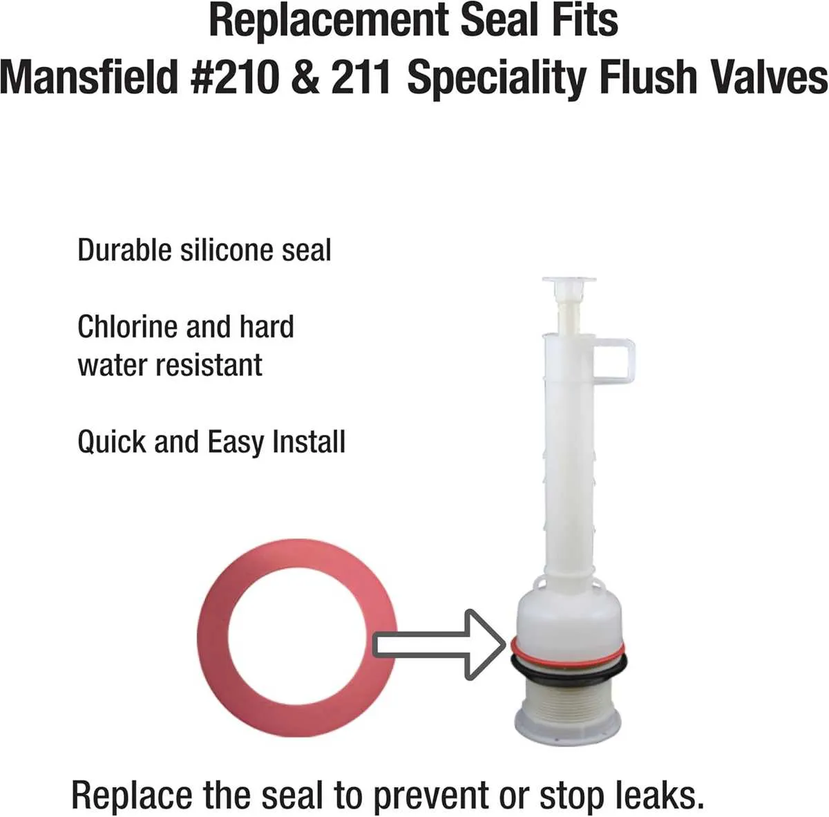
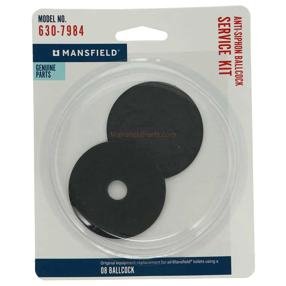
Locating and Matching Seal Sizes for Mansfield Fill Valves

Measure the internal diameter of the refill assembly seat using a precision caliper–common dimensions range from 1.9 to 2.2 inches. Avoid assumptions based on model numbers alone; visual inspection combined with direct measurement yields accurate sizing.
Identify the gasket profile: flat seals are typically used with older refill systems, while cone-shaped variants match newer fluid intake assemblies. Check for raised ridges or tapered edges that indicate specific compatibility.
Match materials based on durability. Silicone gaskets resist hard water and chlorine better than standard rubber. For high-use environments, select reinforced seals labeled with EPDM or Viton for extended lifespan.
Compare old and replacement rings side-by-side under adequate lighting. A mismatch as small as 0.1 inch can result in slow leaks or poor refill rates. Ensure the new unit sits flush in the valve seat without visible distortion.
Consult the underside of the tank lid for stamped component codes. These may reference compatible seal dimensions or identify specific refill assemblies requiring proprietary sizes. When codes are absent, bring the old gasket to a hardware supplier for direct fit verification.
Understanding Trip Lever Variations in Tank Assemblies
Install a 7″ brass lever arm (part code BLA-7) for durable engagement on vitreous porcelain cisterns, ensuring a 45° sweep for efficient water release. Opt for stainless steel models when handling high-mineral-content supply lines to prevent corrosion and maintain smooth pivot action. Thread engagement must match a 5/16″-18 brass coupling nut to avoid wobble and leaking at the seal interface.
Select left- or right-hand configurations based on handle placement: LH-500 series for wall-adjacent installations, RH-500 for open-wall setups. Verify handle throw of 1¼″ to achieve full valve lift without slamming or incomplete closure. For heavy-flow systems, upgrade to the 900 series zinc alloy lever with reinforced bushings for added longevity under repeated cycling.
When swapping assemblies, measure existing stem length–standard stems are 2¼″, extended reach stems up to 4″ for deep-set reservoirs. Lubricate pivot points with food-grade silicone grease to reduce metal-on-metal wear. Confirm smooth operation by cycling the handle 20 times; any resistance beyond light spring tension indicates misalignment or foreign debris in the valve seat.