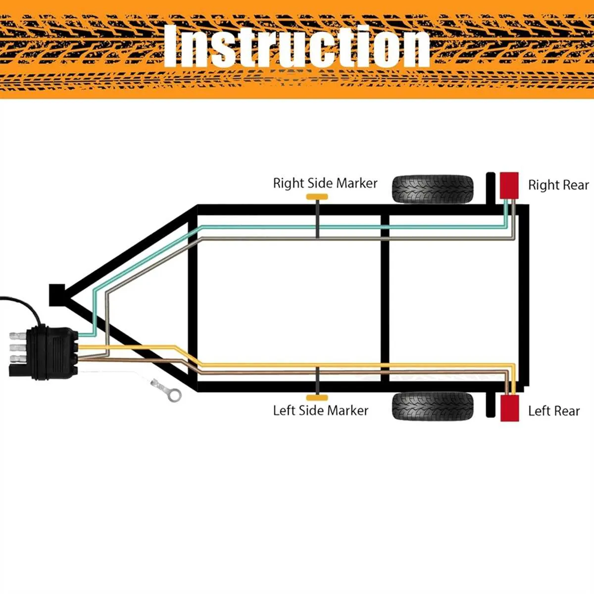
If you need to connect a five-pin system to a four-pin setup, the process involves a simple but essential adjustment. This modification ensures proper signal transmission between the towing vehicle and the attached load. The key is understanding the pin assignments and matching them correctly. You’ll use one of the unused pins to bridge the gap and maintain full functionality.
Start by identifying the functions of each terminal in your existing five-pin configuration. Typically, these include left and right turn signals, brake lights, ground, and reverse lights. The goal is to map these functions to a four-pin system that typically supports left and right turn signals, brake lights, and ground only. The reverse light feature is often omitted or handled differently in some cases.
Step 1: Disconnect the power source before making any changes. Ensure that all components are powered down to avoid short circuits or damage. Step 2: Use a compatible adapter or reroute the specific connections, ensuring that the reverse signal, if needed, is ignored or properly terminated. Step 3: Test the new connections thoroughly to confirm that all signals function as expected.
By following this approach, you’ll avoid errors in connectivity and prevent potential issues during towing, ensuring safety and reliability on the road.
5 Pin to 4 Pin Conversion Guide
When transitioning from a 5-pin system to a 4-pin connection, start by identifying the purpose of each pin in both setups. The 5-pin configuration typically includes signals for left and right turn signals, brake lights, running lights, and a ground, along with an additional pin for auxiliary functions such as reverse lights or electric brakes.
To simplify to a 4-pin configuration, combine the auxiliary pin with one of the turn signal connections. This is commonly done by linking the reverse or brake signal to the left or right turn signal pin. Ensure the ground is properly connected to the designated terminal and that the tail light signal is separated from the combined turn/brake signal if required by your application.
Test the system after modification to ensure all essential functions, including turning, braking, and illumination, are operating as expected. This conversion should not affect the core operations, provided the correct connections are made, and the setup is properly grounded.
Understanding the Color Code for 5-Conductor and 4-Conductor Systems
When transitioning between 5-conductor and 4-conductor systems, it’s crucial to correctly interpret the color coding to ensure proper function. Here’s a breakdown of what each color represents in both setups:
5-Conductor Setup:
- Brown: Right turn signal and brake lights.
- Green: Left turn signal and brake lights.
- Yellow: Tail lights and running lights.
- White: Ground connection.
- Blue: Auxiliary power (for electric brakes or other accessories).
4-Conductor Setup:
- Brown: Tail lights and running lights.
- Green: Right turn signal and brake lights.
- Yellow: Left turn signal and brake lights.
- White: Ground connection.
Important Tip: In the absence of a blue conductor, a 4-conductor system doesn’t support auxiliary power features such as electric brakes. Ensure to check the system’s specifications if auxiliary functionality is required.
By recognizing these color codes, the switch from a 5-conductor to a 4-conductor system is straightforward, but always double-check connections to avoid malfunctions.
Step-by-Step Guide to Converting 5-Wire to 4-Wire Trailer Wiring
Start by identifying the functions of each conductor in the 5-pin setup: left turn signal, right turn signal, brake light, ground, and auxiliary. The first three conductors correspond to essential lighting functions, while the ground and auxiliary can be combined to form the fourth line for the 4-pin version.
To convert, connect the ground wire from the 5-pin system to the common ground in the 4-pin setup. Next, combine the left turn and brake signals into a single connection. Do the same with the right turn and brake signals, ensuring that the system operates with the correct polarity.
For the remaining pin in the 4-pin configuration, assign the auxiliary function, if needed, or simply leave it unused if the system doesn’t require it. Finally, ensure that the grounding is secure to avoid electrical faults.
Test the connections to confirm proper function before finalizing the setup, checking that each signal is correctly relayed through the adapted system.
Troubleshooting Common Issues in 5-to-4 Circuit Conversion
When converting from a 5-circuit setup to a 4-circuit system, several common problems may arise. Addressing these issues promptly will ensure safe and efficient operation of your connection. Here’s a focused guide on how to troubleshoot and resolve typical challenges:
- Loss of Signal on Running Lights: Ensure that the connection from the tail light (often the brown or yellow) to the converter is secure. If the running lights are not illuminating, check for a poor connection or damage to the converter.
- Brake Lights Not Functioning: Verify that the signal from the brake circuit (usually green or red) is properly routed. Use a multimeter to confirm power is reaching the correct pin at the junction box.
- Turn Signal Malfunctions: The most common issue is a misdirected connection between the left and right signal circuits. Double-check that the green and yellow signals are correctly matched to the vehicle’s output terminals.
- Grounding Issues: Inadequate grounding is a common cause of malfunction. Inspect the ground connection at the vehicle end to ensure it is clean, corrosion-free, and firmly connected. Poor grounding often results in flickering or intermittent signals.
- Converter Overheating: Overheating may occur if the converter is not properly rated for the load. Make sure you’re using a unit that matches the amperage requirement. If overheating persists, consider upgrading to a more robust converter.
Regularly testing the integrity of connections with a circuit tester and ensuring all components are securely attached will prevent many issues from arising during the conversion process. Troubleshoot step by step and avoid rushing through each stage.