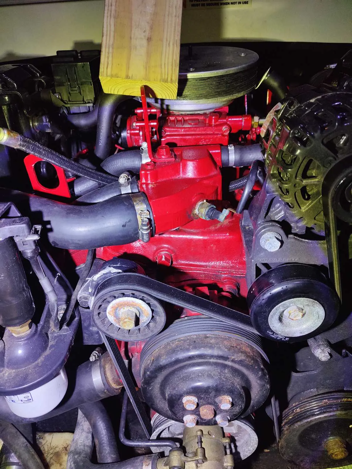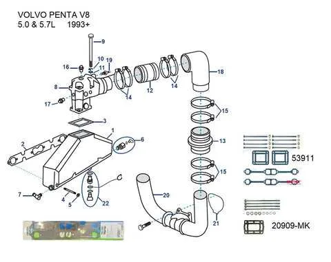
For optimal engine performance, proper alignment and sealing of the cooling system components are crucial. One of the primary elements to check is the part responsible for regulating coolant flow. Ensure that the gasket and seals are intact to prevent leaks and overheating issues. Incorrect installation or damaged components can lead to fluid loss and, eventually, engine damage.
Inspection of the assembly should begin with verifying the positioning of all attachment points. Make sure the component securing the fluid channels is mounted firmly. A loose connection will lead to pressure loss, impacting the engine’s ability to stay within safe operating temperatures.
Attention should also be given to the intake and outflow connections. These connections must be clear of any blockages or corrosion, as this could restrict the coolant flow, reducing efficiency. Always use appropriate seals and ensure they are positioned correctly to avoid leaks or failure under pressure.
When replacing any part of the system, double-check the fitment and torque specifications as per the manufacturer’s guidelines. Over-tightening can cause cracks, while under-tightening can lead to fluid leaks. Proper installation will ensure a long-lasting and efficient engine cooling cycle.
Engine Cooling System Components and Assembly
Ensure proper placement of the temperature regulation unit by aligning it correctly with the engine block. The following steps outline the key elements to be aware of when assembling or inspecting the cooling system part responsible for temperature control.
- Seal Integrity: Always check the gasket for any signs of wear or damage before installation. A compromised seal can lead to leaks and overheating.
- Alignment of Ports: Ensure that all inlet and outlet connections are aligned to prevent flow disruption. Any misalignment can affect the engine’s cooling efficiency.
- Material Quality: Inspect the component for cracks or corrosion, especially around areas exposed to constant heat cycles. Consider replacing if there is noticeable wear.
- Fastening Torque: Tighten the securing bolts to the specified torque. Over-tightening can damage the threads or cause cracking, while under-tightening may result in a loose fit and leaks.
For optimal operation, ensure that the part is oriented in the correct direction relative to the engine’s cooling flow. Improper installation can result in inefficient cooling and potential engine damage.
- Start by cleaning the contact surfaces thoroughly to remove old gasket material.
- Place the new gasket and align the part correctly with the engine block.
- Secure the part with the appropriate fasteners, ensuring all bolts are tightened in a crisscross pattern for even pressure distribution.
Periodically inspect this part to ensure proper function. A malfunctioning unit can lead to engine overheating and system failure.
Locating Key Components of the Thermostat Assembly
Start by identifying the coolant inlet and outlet ports on the assembly. These are critical for ensuring proper fluid flow during engine operation. The inlet is typically located on the side of the unit, while the outlet is positioned at a 90-degree angle to direct fluid to the engine block.
Next, locate the temperature sensor. It is usually attached to the top section of the assembly and is responsible for monitoring the engine’s heat level. This sensor connects directly to the control module, ensuring the engine doesn’t overheat.
The bypass valve can be found near the lower part of the unit. It allows coolant to circulate when the engine is cold, ensuring that the motor warms up efficiently. This component is essential for maintaining optimal engine temperature during start-up.
Lastly, the mounting bolts that secure the assembly to the engine block must be located. These are typically situated around the perimeter of the unit and should be checked for tightness and corrosion regularly to maintain a leak-free seal.
Understanding the Flow Path for Coolant in the Thermostat System

Begin by ensuring the outlet from the upper coolant chamber connects directly to the primary mixing junction leading to the heat exchanger. This guarantees initial circulation bypasses external loops until internal temperature thresholds are met.
Cool fluid is drawn from the lower pump intake, routed through block jackets, and rises via internal channels to reach the control valve assembly. When internal fluid exceeds 160°F (71°C), the wax capsule actuator expands, shifting the gate to open flow toward the exchanger port.
At this stage, heated liquid is redirected externally for thermal regulation. Excess bypass is blocked by a seated plunger, forcing all output through the exchanger loop. Once temperature drops, the actuator contracts, sealing the external path and reopening internal circulation.
For optimal performance, confirm the crossover channel is clear, and the bypass loop contains no restrictions. Any clog within the recirculation arm can cause overheating due to delayed pressure relief or insufficient flow velocity through the core.
Identifying Common Issues and Troubleshooting Thermostat Housing Connections

Start by checking for corrosion around the neck where coolant pipes connect; green or white deposits indicate electrolysis or poor grounding. Clean thoroughly and apply dielectric grease during reassembly to prevent recurrence.
If coolant seeps from the joint between the upper outlet and the metal shell, inspect for a warped mating surface. Use a straight edge to detect irregularities; light resurfacing may be needed to restore a proper seal.
When overheating persists despite a new valve insert, confirm the bypass port isn’t blocked by gasket misalignment or sealant overflow. Clear any obstructions and ensure ports are fully open during reassembly.
Loose hose clamps often mimic more severe problems. Tighten all bands to manufacturer torque spec, usually 30–40 in-lbs. Avoid overtightening, which may crack plastic collars or distort aluminum flanges.
For units with dual outlets, confirm the Y-fitting is free of internal scale or rust. Use a flexible bore scope if access is limited. Clogs here often lead to erratic cooling or backflow under high load.
Hairline fractures near mounting bolts can cause pressure loss without visible leaks. Run a cold-pressure test at 15 psi and monitor for slow drops. UV dye may help locate microleaks during operation.