For proper functionality, ensure all connections to the starting system are correct. Begin by confirming that the power is correctly routed from the battery to the control unit, enabling the vehicle to power on when activated. This setup typically involves a series of relays and fuses, which need to be checked for continuity and resistance.
Focus on the control points where the key or electronic device engages with the main circuitry. These areas are critical for initiating the electrical flow to the engine. Any malfunction here can result in issues such as failure to start or inconsistent operation. Inspect each terminal for corrosion and wear that could disrupt the process.
The connection between the starter and the electrical system must be tightly secured to avoid loss of signal during activation. A poor connection can prevent the engine from receiving the necessary current, causing the vehicle to remain inoperable. Regular inspection and maintenance of these components can prevent common issues.
Verify the position of the control elements to ensure they match the intended operational configuration. This includes confirming that each pin on the device aligns with the corresponding signal or power line it is supposed to control. Misalignment could lead to short circuits or improper triggering of the engine-start process.
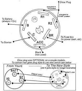
Electrical Connection Layout for Starting Mechanism
For accurate installation and troubleshooting of the starting mechanism, follow these precise connections:
- Position 1: The primary terminal should be linked to the battery’s positive terminal. Ensure the wire is properly insulated to prevent short circuits.
- Position 2: The secondary terminal connects to the power relay, providing current flow when the mechanism is activated.
- Position 3: A connection to the vehicle’s electrical control unit (ECU) is necessary for the signal transmission to start the engine.
- Position 4: The auxiliary terminals must connect to the dashboard panel or other control systems, ensuring proper feedback signals during operation.
Be sure to use high-quality connectors to avoid resistance that could lead to malfunction. Verify all wires are securely attached, and test the system after installation for any loose connections or electrical faults.
In case of malfunction, check for continuity using a multimeter to ensure all paths are complete. If there’s no response from the power relay, inspect the connections at the terminals for corrosion or wear.
Understanding the Basic Pinout of an Ignition Switch
To ensure proper functionality, focus on correctly wiring each terminal based on its function. Typically, you’ll find four main pins in this component: Power, Start, Accessory, and Ground.
The Power pin connects to the main power supply of the vehicle, delivering voltage when the system is engaged. The Start pin is activated when turning the key to initiate the engine’s cranking sequence. The Accessory pin is used to power on auxiliary systems like the radio or lights when the key is in the ‘On’ or ‘Accessory’ position. Lastly, the Ground pin serves as the return path for the electrical current.
To avoid wiring issues, ensure that each terminal is connected according to the manufacturer’s specifications. Using a multimeter to check continuity between pins can help verify proper wiring before installation.
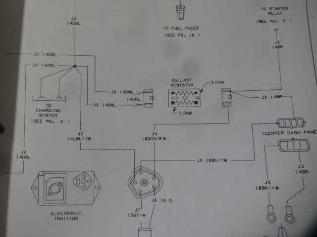
Identifying Common Wiring Errors in Ignition Circuit Schematics

Ensure all connections are properly seated and secured. A common mistake is loose or poorly connected terminals, leading to inconsistent power flow or failure to start the vehicle. Always double-check the wiring for signs of corrosion, especially around terminals that are exposed to moisture.
Verify the correct use of wire gauges. Using wires that are too thin can cause overheating and lead to a fire hazard. Cross-check the recommended wire size for each connection, and avoid shortcuts by using cheaper, inappropriate alternatives.
Incorrectly labeled wires can confuse troubleshooting efforts. Always match each wire to the exact specification on the schematic. Misplaced wires can cause the vehicle’s electrical components to malfunction, so accuracy in identification is essential.
Ensure proper grounding for the system. A poor ground connection often results in a range of electrical issues, from flickering lights to failure to turn on. Inspect ground wires for secure attachment to a clean, unpainted metal surface to prevent voltage drops.
Crossed or shorted connections between different circuits can lead to failures or even damage electrical components. Pay particular attention to connections that could potentially contact metal parts, especially if insulation is compromised.
Troubleshooting Electrical Issues with the Starting Mechanism
Start by verifying the electrical connections. Check for loose or corroded terminals at the starting mechanism, especially at the primary power source and relay points. Ensure all wires are properly attached and show no signs of wear or shorting.
Next, examine the continuity of the circuit. Use a multimeter to test the continuity from the power input to the actuator. A lack of continuity indicates a broken circuit, often caused by damaged wires or components.
If the system does not engage, check the locking mechanism. Ensure that all internal components are moving freely and not obstructed. Misalignment can prevent proper contact and lead to system failure.
In cases where the control component fails to engage properly, inspect the mechanical elements for wear. A worn-out contact plate or internal pin may fail to complete the circuit, resulting in malfunction.
Finally, confirm the proper operation of the relay and fuses. A malfunctioning relay or a blown fuse can interrupt the electrical flow, preventing the system from initiating. Replace any defective relays or fuses to restore functionality.