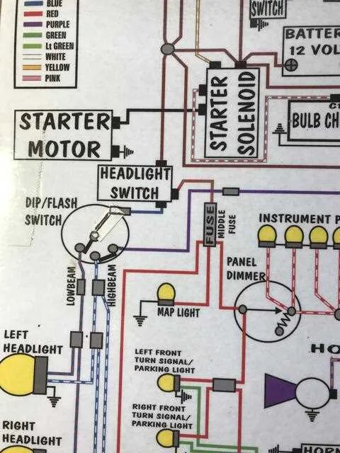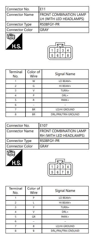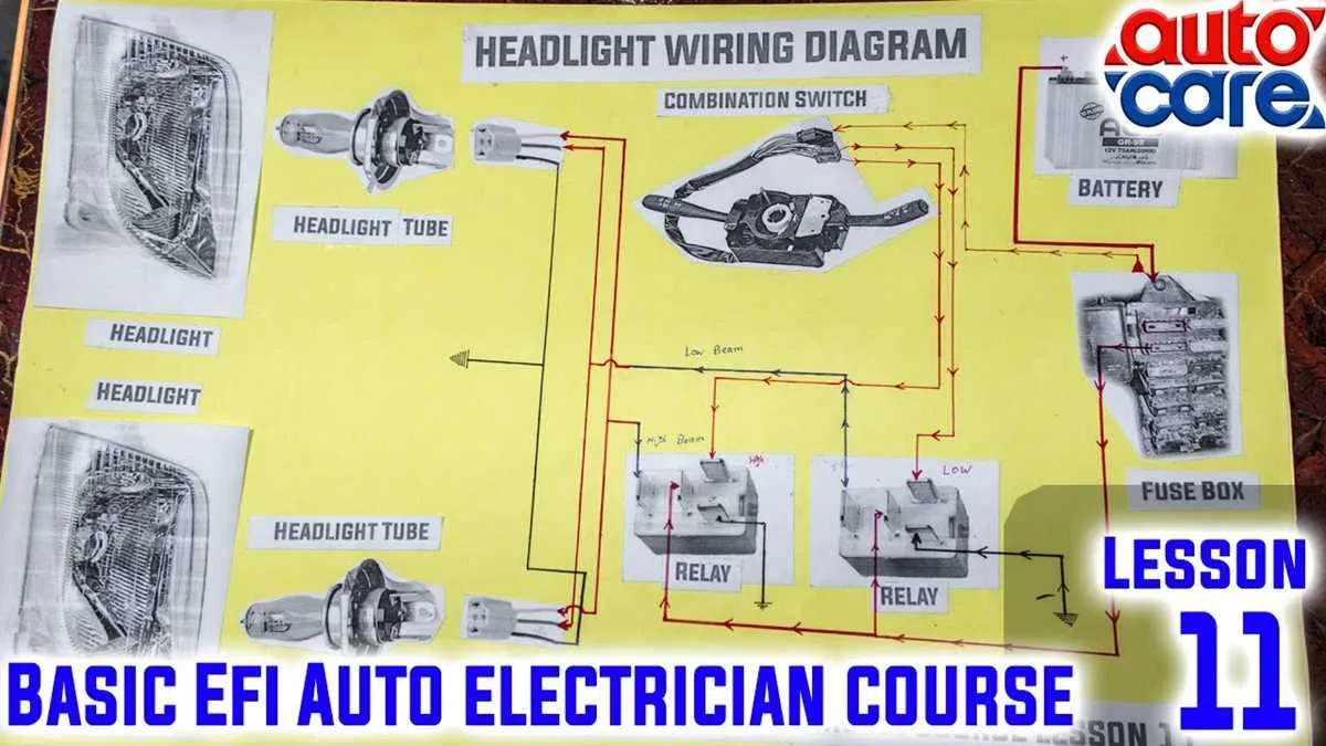
For reliable operation of your vehicle’s front lighting assembly, ensure correct identification of power, ground, and control signal lines. The main power feed typically comes directly from the battery through a fuse, while the control circuit is managed via the lighting switch or an automatic sensor module.
Positive supply wires usually feature a specific color code–often red or yellow–indicating constant or switched power sources. Ground connections are critical for completing the circuit and are commonly represented by black or brown cables connected to the chassis.
Signal lines for low and high beam functions run separately to the bulb socket, controlled by relays or switches to prevent circuit overloads. Correctly routing and connecting these ensures optimal brightness and longevity of the bulbs.
For models with integrated daytime running lights or adaptive features, additional conductors may be present and require careful matching according to the manufacturer’s specification to maintain system integrity and safety.
Connection Layout for Vehicle Front Lighting
For proper assembly of the front illumination system, ensure the following key points:
- Use a 12V power source with a dedicated fuse rated between 10A and 15A to protect the circuit.
- Connect the positive lead from the battery to the switch controlling low and high beam modes.
- Ground the negative terminal directly to the vehicle chassis to avoid voltage drops.
- Incorporate a relay between the power supply and the lighting unit to reduce load on the switch and prevent overheating.
The typical conductor assignments include:
- Low beam wire: Usually marked with blue or white insulation; connect to the low illumination filament.
- High beam wire: Often red or green; runs to the filament responsible for intense lighting.
- Ground line: Black or brown cable providing negative return path.
- Indicator or parking lamp feed: Yellow or orange wire, if integrated into the unit.
For optimal functionality, use automotive-grade connectors with secure locking mechanisms. Avoid exposed splices by utilizing soldering or crimp terminals sealed with heat shrink tubing.
Verify circuit continuity with a multimeter before final assembly and test switching operations under engine running conditions to ensure voltage stability.
Step-by-Step Process to Trace and Repair Headlight Wiring

Begin by disconnecting the battery to prevent electrical hazards. Locate the main connector that supplies power to the front lighting assembly. Using a multimeter set to continuity mode, test each conductor from the plug towards the bulb socket to identify any breaks or shorts.
Mark each faulty section found during testing. Inspect the insulation along the entire length for abrasions or burns, especially near mounting points and moving parts. Use a wiring tracer or test light to follow the power path if the cable bundle is complex or bundled with other circuits.
For damaged leads, cut out the compromised area and strip the insulation on both ends by about 6 mm. Employ soldering with heat shrink tubing for reliable reconnection rather than twist or crimp methods. Ensure connections are waterproof, especially if exposed to moisture.
Check grounding points by measuring resistance between the negative lead and the chassis; it should be close to zero ohms. Clean and tighten any corroded terminals to restore a stable ground path.
After repairs, reconnect the battery and test the lighting function using the vehicle’s control switch. Confirm consistent illumination without flickering or dimming. Finally, secure all cables with zip ties or clips to prevent movement and future wear.
Common Faults and How to Diagnose Them in Vehicle Front Lighting Systems

Check for loose or corroded connectors first. These are the primary causes of intermittent or complete failure of the illumination units. Use a multimeter to verify continuity and voltage at each terminal, ensuring stable power supply.
Inspect grounding points thoroughly. Poor earthing often results in flickering or dim lights. Clean any rust or oxidation on the metal contacts and tighten all bolts securing the grounding wires.
Look for damaged insulation and broken conductors. Frayed or exposed conductors can cause short circuits or open circuits. Trace the harness along the frame and flex the cables gently while measuring voltage drop to detect hidden breaks.
Test the control switches and relays. A malfunctioning switch or relay can prevent power delivery to the bulbs. Use a test lamp or a multimeter to confirm activation and proper operation under load conditions.
Use specialized diagnostic tools when available. An oscilloscope or automotive scanner can help identify transient faults or abnormal voltage fluctuations within the front illumination circuit.
Replace faulty bulbs or sockets without delay. Burnt-out filaments or oxidized socket contacts reduce light output or cause flickering, impacting safety and visibility.