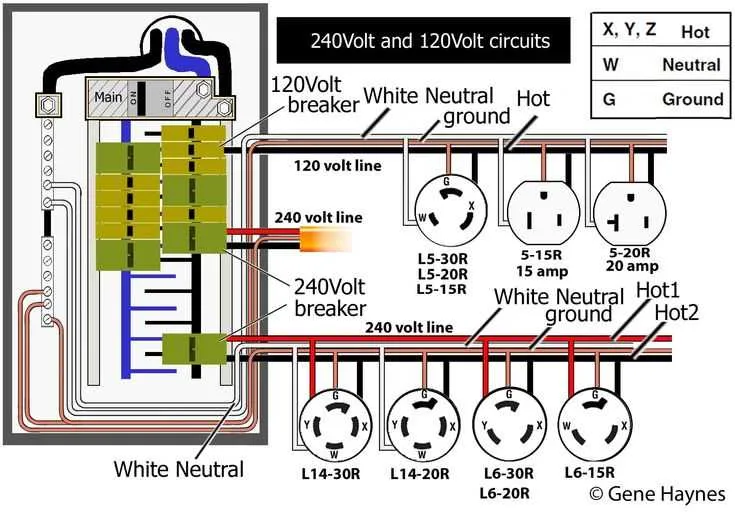
When installing a 30-amp outlet for 120/240V circuits, it’s crucial to follow specific procedures to ensure safety and proper functionality. A three-prong or four-prong connector is typically used, depending on whether ground and neutral are separate in your installation. Make sure the circuit breaker matches the amperage and the gauge of the wire is correct for the load.
Ensure the wiring is connected securely to prevent any risk of overheating or electrical fires. A hot wire (usually black or red) connects to the terminal marked for it, while the neutral wire (white) should be placed on the corresponding terminal. If your system requires a ground, this should be attached to the green terminal.
Verify that the installation complies with local electrical codes and that all connections are tight, as loose wires can cause arcing. Always double-check the correct polarity by using a voltage tester once the system is energized.
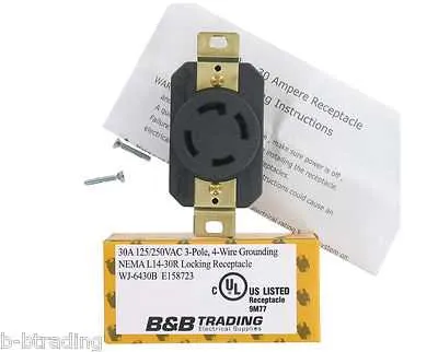
Wiring Instructions for 30A Twist-Lock Connector
For a proper electrical connection, connect the four terminal leads as follows: the black lead (hot) should be wired to the brass terminal, the white lead (neutral) to the silver terminal, and the two ground wires should be connected to the green terminal. Ensure the ground conductors are tightly secured and free from any insulation damage to avoid potential faults.
When connecting the live wire, double-check the terminal for any corrosion or wear. If necessary, clean the metal contact points before securing the wire. The male and female connectors should align properly to guarantee a tight and secure fit. Use appropriate gauge wire to match the amperage rating and verify the entire setup with a continuity test before activating the circuit.
Ensure the installation complies with local electrical codes, and always turn off the power at the circuit breaker before working on any connections. After installation, use a voltage tester to confirm that the power flows as expected and that all connections are secure.
Understanding the 30A 4-Prong Plug and Receptacle Pinout

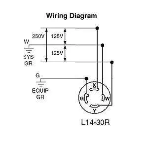
For proper installation, follow the color coding and ensure a secure connection to avoid electrical hazards. The 30A 4-prong connectors are designed to support 120/240V systems, typically used in high-power appliances like welders and RVs. Here’s the breakdown of the prongs:
Hot (Line) 1: The first hot terminal is the black wire. It carries 120V, and it is paired with the second hot terminal to supply 240V when connected. This prong is on the left side of the receptacle, looking directly at it.
Hot (Line) 2: Located directly opposite the first hot terminal, the red wire connects to the second 120V hot prong. When both hot lines are connected, they deliver the required 240V for equipment requiring more power.
Neutral: The neutral terminal is represented by the silver-colored prong. It is the ground return path for electrical current, often connected to the white wire in the plug. The neutral prong ensures the balance of the current flow between the two hot wires.
Ground: The ground prong is the round, green or bare wire terminal. This is a safety feature, ensuring any stray electrical current is safely directed to the ground, minimizing the risk of shock or fire.
Remember to verify the connections with a voltage tester after installation to ensure all connections are made properly before use.
Step-by-Step Guide to Installing a 30-Amp 4-Prong 240V Outlet
1. Turn off the power: Before starting, ensure the main power supply is switched off at the breaker panel. Verify no current is flowing using a voltage tester.
2. Prepare the outlet box: Install the outlet box securely at the desired location, ensuring it meets local electrical codes. It should be firmly attached to the wall studs.
3. Cut the cable: Use a cable with at least 10-gauge wire for the 240V circuit. Cut it to the required length to reach from the breaker panel to the outlet box, leaving extra for stripping.
4. Strip the wires: Remove approximately 6-8 inches of the outer insulation from the cable. Strip about 1/2 inch of insulation from each individual wire–black, white, and ground.
5. Connect the black (hot) wire: Attach the black wire to the brass terminal on the outlet. Tighten the screw to secure the wire, ensuring no bare copper is exposed.
6. Connect the white (neutral) wire: The white wire goes to the silver terminal on the outlet. Again, make sure the wire is firmly attached and no copper is exposed.
7. Attach the ground wire: The green or bare copper ground wire should be connected to the green terminal on the outlet. Tighten the screw to ensure a solid connection.
8. Secure the outlet to the box: Once all wires are attached, carefully tuck them into the outlet box. Attach the outlet to the box using the provided screws. Ensure the outlet is level and flush with the wall surface.
9. Connect the circuit breaker: At the breaker panel, attach the black wire to the 30-amp double-pole breaker and the white wire to the neutral bus bar. The ground wire should be attached to the ground bar.
10. Test the installation: Turn the power back on at the breaker panel and use a circuit tester to confirm the outlet is properly wired and operational.
Common Mistakes to Avoid When Wiring NEMA L14-30

Here are the critical errors to steer clear of during installation:
- Incorrect Wire Size: Always use 10 AWG wire for the connections. Using smaller gauge wire may cause overheating and electrical hazards.
- Improper Grounding: Ensure the ground wire is properly connected. An ungrounded outlet can lead to serious safety risks, including electrocution.
- Wrong Connector Type: Confirm that the plug and receptacle are the correct type for the system. Misconnections can lead to shorts or damage to appliances.
- Neglecting to Turn Off Power: Before beginning any work, always ensure the breaker is off. Working on live circuits can result in injury or equipment failure.
- Forgetting to Tighten Screws Properly: Loose connections can cause electrical arcing or even fires. Double-check that each terminal screw is securely tightened.
- Incorrect Phase Alignment: Pay attention to the proper arrangement of the hot, neutral, and ground wires. Misplacing any of these can cause malfunction or electrical shock.
- Using Old or Worn-Out Equipment: If any components appear damaged or outdated, replace them before installation. Faulty parts can compromise system safety.
- Failing to Follow Local Codes: Adhere strictly to electrical codes for your area. Non-compliance can result in penalties or hazards.
- Overloading Circuit: Always ensure that the circuit’s load does not exceed the rated amperage. Overloading can lead to overheating and system failure.
By avoiding these common pitfalls, you ensure a safer and more efficient setup for your electrical system.