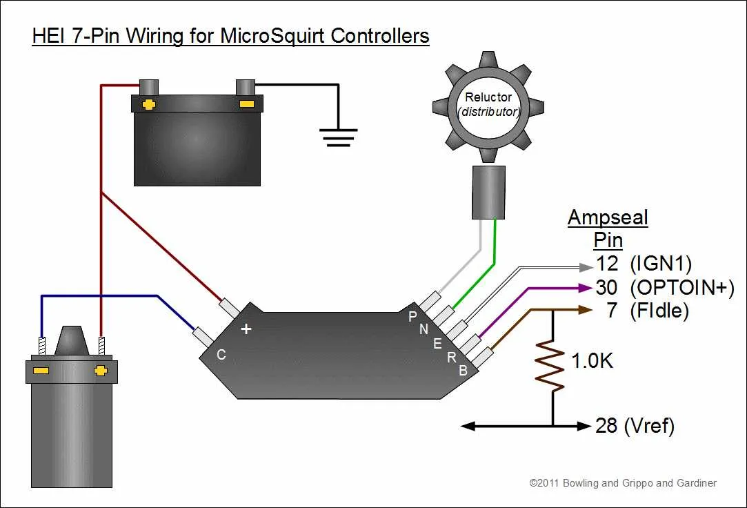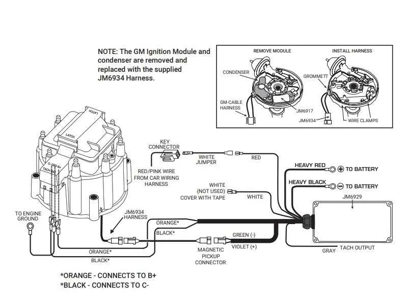
When working on your vehicle’s electrical setup, precise connections are essential for optimal performance. Start by ensuring that your primary power wire is securely attached to the main terminal of the unit. Use a 12-volt power source for reliable current flow. The connection between the power source and the system’s ignition terminal must be firm and free of corrosion, which could hinder the spark timing.
Next, the ground wire must be connected to the engine block or a nearby metal part that ensures a solid electrical return. A poor ground connection can result in weak or inconsistent firing, leading to inefficient engine performance. Verify the grounding by checking the resistance with a multimeter before moving on.
Connect the signal wire to the coil for spark control, making sure that the insulation is intact and the wire is not exposed to heat or abrasion. This wire controls the ignition sequence and must be routed carefully to avoid interference from other components. Improper routing could lead to misfires or other engine issues.
For accurate timing, adjust the unit according to the manufacturer’s specifications. A correctly calibrated system will provide steady power to the ignition coil, ensuring your engine runs smoothly. Always double-check your connections and consult a professional if you’re uncertain about the setup to avoid damage or performance loss.
Wiring Setup for a GM 350 V8 Engine’s Electronic Spark Control System

For proper engine performance, connect the power source to the terminal marked with a “+” sign, ensuring it runs to the coil positive terminal. Use 12V power, ideally from a switch that activates when the engine is running.
The negative terminal of the coil connects to the control module, which regulates the spark timing. Make sure the control unit is securely mounted, and all connections are tight to avoid misfires or weak sparks.
The sensor lead, typically a two-wire setup, should be routed to the pickup coil. One wire goes to the sensor’s signal input, while the other is grounded on the chassis or engine block.
Ensure that the tachometer signal is routed from the system’s output terminal to the gauge or signal receiving unit. This allows you to monitor engine revolutions per minute, ensuring proper RPM operation.
If your system includes a vacuum advance unit, it must be plumbed correctly to the intake manifold to adjust the timing based on engine load. This fine-tunes performance and fuel efficiency at varying speeds.
How to Properly Wire the Ignition System for a Chevy 350 Engine
To ensure proper function of your engine’s ignition system, begin by connecting the main power wire to the positive terminal on the coil. This will provide necessary voltage for the spark. Make sure this wire is routed securely to avoid interference with other components. Next, the ground wire must be attached to a clean, bare metal surface on the engine block. This ensures proper grounding for the ignition system, preventing misfires and voltage issues.
The next step is to hook up the signal wire from the engine control module to the coil. This wire is essential for triggering the timing sequence. Make sure to use the correct gauge for this connection to ensure accurate signals are transmitted without delay or loss of power. You should also install a proper connector to avoid wear and prevent electrical shorts.
For the final step, connect the tachometer wire from the ignition unit to the engine’s dashboard gauge if applicable. This will allow you to monitor the engine’s revolutions per minute (RPM) accurately. Ensure that this connection is tight and secure to maintain reliable readings over time.
Lastly, verify all connections before starting the engine. Check for any loose or poorly connected wires, as these can cause major issues such as weak sparks or irregular engine performance. Tighten all screws and connections, and test the system to confirm everything is functioning as expected.
Understanding the Role of the Ground and Power Connections
To ensure proper engine performance and electrical efficiency, the ground and power connections are crucial in any ignition system setup. These connections provide the necessary pathways for electrical flow and stability. Below are the essential points to ensure reliable functionality.
- Power Connection: The positive terminal, typically connected to the battery, must be routed directly to the coil or the primary power feed for the ignition system. Ensure this wire is of adequate gauge to prevent power loss or overheating.
- Ground Connection: A clean and solid ground is vital for minimizing electrical interference and ensuring smooth operation. The ground wire should be securely connected to the engine block or chassis, as close to the ignition system as possible.
- Connection Quality: Use corrosion-resistant materials for both power and ground connections to avoid future electrical failures. Tighten all connections properly to prevent voltage drops and poor system performance.
- Wire Routing: Avoid running the power wire parallel to high-voltage cables. This minimizes the risk of electromagnetic interference, which can lead to erratic system behavior.
- Fuse Protection: A fuse should be placed in-line with the power wire to prevent potential short circuits. Use an appropriate amperage rating for the fuse to protect the ignition system components.
- System Testing: After installation, use a multimeter to verify voltage at the coil and the ground. Check for consistent readings, and ensure that no voltage fluctuations occur under normal operating conditions.
Proper attention to both ground and power connections ensures that your ignition system operates without issue and provides reliable performance over time.
Common Mistakes When Connecting the Ignition System and How to Avoid Them
Ensure proper connection of the power wire to the correct terminal. Failing to attach the power lead to the “BAT” terminal often causes weak spark or no spark at all. Double-check the wiring to avoid this issue.
Avoid grounding the coil or control unit through incorrect placement of the grounding wire. Misplacement can lead to electrical shorts, causing system failure. Always secure the ground wire to a clean, unpainted metal surface.
Do not neglect the use of a resistor if your setup requires one. Some setups need a ballast resistor to prevent excessive current, while others do not. Running the system without a resistor or with the wrong type can damage the module and reduce lifespan.
Incorrect timing adjustments can lead to poor engine performance and even damage the internal components. Use a timing light to ensure proper synchronization between the rotor and coil. Double-check that the rotor is aligned correctly before securing the assembly.
Avoid poor quality connectors that might lead to corrosion and loose connections over time. Using high-quality, properly sealed connectors will ensure reliable performance and prevent electrical issues.
Do not skip verifying the voltage input to the system. A voltage drop or excessive voltage can disrupt the spark and cause misfires. Always check the voltage levels to ensure that they fall within the system’s specified range.