When working on electrical systems in vehicles or machinery, it’s crucial to understand the connections within a 5-terminal setup. This configuration is commonly used to control multiple functions simultaneously, including engine start and power distribution to essential components. By correctly identifying and connecting each terminal, you can ensure reliable operation and prevent potential short circuits or malfunctions.
Begin by identifying the main power input terminal, typically the central connection that brings current to the system. Next, focus on the outputs, each linked to different components like the fuel system, lights, or other devices. Understanding how each connection influences the overall system can help you troubleshoot issues more effectively and streamline the installation process.
Make sure to verify the grounding terminal as well. A proper ground is necessary to complete the circuit and ensure that all components function as intended. It’s important to check that all connections are securely fastened, as loose or poorly connected terminals can lead to intermittent failures.
Additionally, always refer to the specific vehicle or equipment manual to match the terminals with their designated functions. Misconnections can cause damage to sensitive components, leading to expensive repairs. By following the correct order and guidelines, you can set up the system with precision and avoid common installation errors.
Understanding the 5-Terminal Electrical Connection Setup

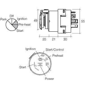
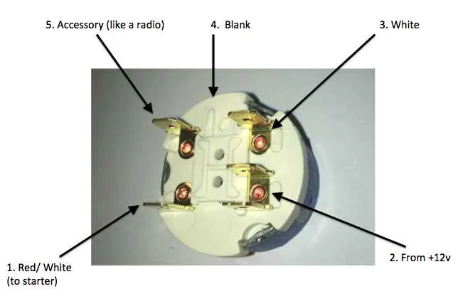
For a secure connection between multiple components, ensure that each terminal is properly aligned with its corresponding wire. Begin by identifying the first terminal, typically used for power input, which provides energy flow to the system. The second terminal serves as a link to the main circuit, enabling it to activate under specific conditions. The third terminal is connected to the start-up mechanism, which can either trigger the system’s operation or control certain activation phases. The fourth terminal often serves as a grounding point, redirecting any excess current or energy away from the primary circuit. Finally, the fifth terminal is responsible for controlling auxiliary components, like lighting or additional safety features.
Verify the connections before applying power to avoid misfires or electrical shorts. Use a multimeter to check continuity and ensure that all terminals are properly configured. When working with complex setups, follow the manufacturer’s instructions for the exact positioning of each wire to maintain optimal functionality.
By adhering to this configuration, you will ensure that each terminal is performing its specific function, improving both safety and reliability during operation. Regular inspection of these connections can prevent potential issues related to improper contact or wear over time.
Understanding the 5-Connector Layout

When working with a 5-terminal electrical component for vehicle starting systems, it is crucial to identify each connection’s function accurately. Here’s a detailed breakdown:
- Terminal 1 (Battery Supply): This terminal connects directly to the power source. It provides constant power to the system when the component is active.
- Terminal 2 (Accessory): Used to power accessories such as lights or radios. It is activated when the system is in the “on” position.
- Terminal 3 (Start): This is the crucial terminal for engaging the engine starting circuit. It activates the starter motor when the system is in the start position.
- Terminal 4 (Ignition/Engine Running): Powers the ignition system, allowing the engine to run once started. This terminal is connected to the coil or other ignition components.
- Terminal 5 (Ground): Essential for completing the electrical circuit. This terminal connects to the ground of the vehicle.
Always ensure each wire is connected to the correct terminal to avoid malfunctions. Verify continuity and correct voltage levels before testing the system to prevent any damage to components.
Understanding this layout helps maintain safety and reliability when installing or repairing the system. Double-check all connections to ensure optimal performance.
Step-by-Step Guide to Wiring Each Terminal on the 5 Terminal Mechanism
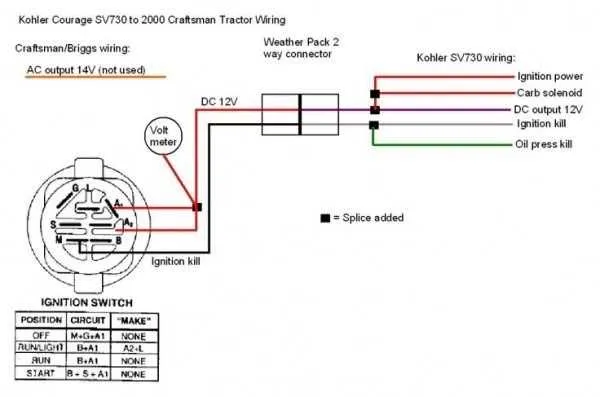
Begin by identifying the first terminal, typically marked with the letter “S”. Connect this to the starter motor. This terminal controls the power flow needed to turn the engine over.
Next, locate the terminal marked “B”. This is for the battery connection. Attach the battery’s positive lead here to ensure continuous power supply to the system.
The “I” terminal is used for the ignition system. It is essential for providing power to the ignition coil. Connect the ignition coil’s lead to this terminal.
The fourth terminal is often labeled “L”. This is linked to the lighting circuit. For this connection, run a wire from the terminal to the lights, ensuring they receive power when activated.
Lastly, there is the “R” terminal. This is for the accessory circuit, typically supplying power to radio, air conditioning, or other accessories. Link the accessory power line to this terminal for proper operation.
Troubleshooting Common Issues with 5-Terminal Connection Systems

When facing issues with a 5-terminal setup, start by ensuring all connections are properly secured. Loose or corroded terminals can prevent proper current flow, causing malfunction. Check for any signs of wear or damage on the connectors, and replace any parts that show significant degradation.
If the system fails to activate, verify the continuity of the primary circuit. A broken or faulty connection between the main contacts may be responsible. Use a multimeter to test the resistance between terminals. High resistance indicates a bad connection or faulty component.
When the system powers on but doesn’t operate correctly, inspect the relay or solenoid, if present. A faulty relay can lead to improper operation, and testing it with a known good unit can help isolate the problem.
If the device intermittently works, the issue could be poor contact within the terminals. Cleaning the contact points with a suitable cleaner and re-tightening the connections may resolve the issue.
For systems with multiple functions, ensure that each terminal is wired according to the correct function. Incorrect configuration can lead to erratic behavior or failure to activate specific circuits.
Finally, verify the voltage levels at each terminal using a voltmeter. Inconsistent or low voltage readings can indicate an issue with the power supply or a faulty connection.