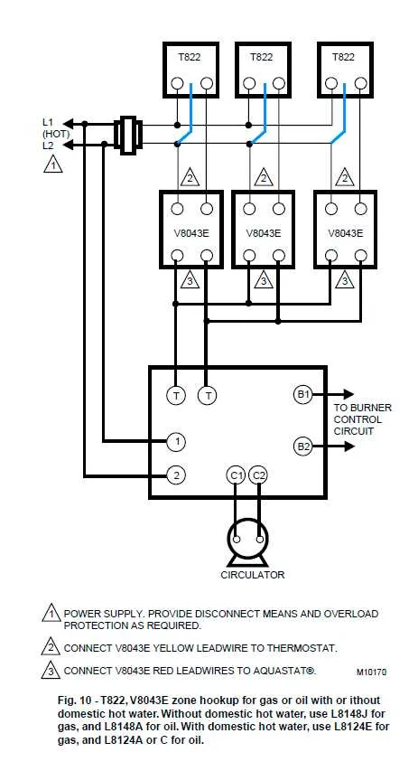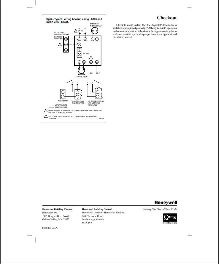
When installing a temperature control relay for a heating system, understanding the proper connection setup is crucial to ensure optimal functionality. Begin by identifying the power source and correctly linking the terminal for the primary control circuit to avoid electrical hazards. Make sure that the wiring follows the recommended color codes for both line and load sides.
First, connect the sensor leads to the designated input terminals. These terminals are typically marked with “S1” and “S2” for sensor connections. Proper calibration can prevent over- or under-heating of the system, ensuring the desired water temperature is maintained. Always verify the sensor resistance using a multimeter before wiring.
Next, link the control’s output terminals to the burner or circulator relay to establish a functional communication path. The configuration of the output should match the system’s requirements: in most cases, a normally open or normally closed switch is used, depending on whether the system calls for an activation or deactivation of the heating element when the temperature threshold is met.
Double-check all connections to prevent short circuits or incorrect operation. Using a heat-resistant wire rated for the appropriate voltage and current can extend the lifespan of the system. Additionally, ensure that grounding is performed according to the local electrical codes to prevent electrical interference.
Finally, test the system thoroughly. Before closing the panel, verify that the temperature control switches between the on and off states smoothly, and ensure that no wires are exposed or improperly connected. This step ensures the longevity and safety of the installation.
Installation of Temperature Control System Connections
Ensure that the sensor is properly connected to the control system terminals. The common connection point for most units is typically labeled as “C” or “Common.” This is the return terminal for the low-voltage wire.
For the heat sensor, connect it to the appropriate terminal labeled “W” or “Heat.” This allows the system to activate the heating element once the water temperature reaches the set point.
If there is a need for high limit protection, use the “L1” and “L2” terminals. These correspond to the power input for the system, and they should be wired directly to the source voltage terminals, ensuring that the system is safely powered.
Next, make sure that the “R” terminal (often red) is connected to the power supply, ensuring the system receives the necessary current for activation. Additionally, consider the use of a jumper if your setup requires it to complete the circuit between specific components.
Finally, test the system for continuity and correct function by verifying that all terminals are securely connected and there are no signs of loose wires or faulty connections. Confirm the temperature reading on the control panel matches the desired set points.
How to Connect the Temperature Control to a Boiler System

Start by ensuring that the power supply to the boiler is turned off before beginning installation. Locate the temperature controller near the boiler, ensuring it’s easily accessible for future adjustments.
Connect the controller’s terminal for the heating element to the boiler’s control circuit, typically marked as “C” for common and “W” for heat. Ensure that the wiring is securely attached to prevent any loose connections, which could lead to erratic operation.
Next, wire the sensor to the terminal marked “S” or “Sensor.” This sensor is responsible for detecting the water temperature in the system, and it must be properly placed to measure the heat effectively. Place it within the boiler’s water chamber, ensuring it does not interfere with moving parts or the heat exchanger.
Attach the power wires to the control unit’s power input terminals, usually indicated by “L” (Live) and “N” (Neutral). Confirm the correct voltage for the unit to prevent electrical damage.
For the safety limit switch, connect it to the terminal designated for the safety feature, which is usually marked with “LS” or “LMT.” This component ensures the system shuts off if the water temperature exceeds the safe threshold.
After all connections are made, double-check for proper wire insulation and ensure no wires are exposed. Once secure, restore power and perform a test to ensure the system operates as expected, adjusting the temperature settings for accurate heating control.
Identifying Wire Connections for Heat Control and Safety Features

When working with heat control devices, it’s essential to correctly connect wires to ensure both functionality and safety. Follow these specific steps to identify and secure proper connections.
- Heat Control Connection: This typically involves the thermostat or temperature sensor. Ensure the wire connected to the temperature sensing terminal (often labeled T1 or T2) is routed directly from the heat sensing device to the terminal block.
- Power Supply: The live and neutral wires should be connected to the appropriate terminals, usually marked L (live) and N (neutral), ensuring proper power flow to the system.
- Circulator Control: If the device controls a pump, ensure the wire connected to the pump terminal is securely attached. The circulator control often requires a separate relay to manage the pump operation when the heat system is active.
- Limit Switch Connections: Limit switches, which serve to prevent overheating, should have connections made to the high-temperature limit terminal. Confirm the wire is connected to the correct terminal to activate the limit switch if temperatures exceed safe limits.
- Safety Shutdown Features: Any safety shutdown wire must be linked to the control panel or the primary circuit to trigger an automatic shutdown in case of a fault, such as overheating or low water levels. Check that the connections are properly insulated and free from wear or corrosion.
- Grounding: For safety, ensure the ground wire is securely attached to the designated ground terminal, usually marked with a symbol or the word ‘GND.’ This prevents potential electrical shocks or short circuits.
Once all connections are made, double-check for any loose or improperly secured wires, as this could affect both performance and safety. Always follow the device’s manual for specific terminal labels and wiring instructions.
Troubleshooting Common Electrical Issues with Temperature Control Units
If your temperature control device is malfunctioning, start by checking the power supply. Ensure that the unit is properly connected to the main circuit and that the circuit breaker is functioning. A tripped breaker can be the root cause of the issue.
Next, inspect the terminals for signs of wear or corrosion. Poor connections at the terminal points often cause the system to fail. If there is any visible damage, tighten or replace the wires to restore a solid connection.
Verify the settings on the device. Incorrect temperature adjustments or misaligned switches can prevent the system from operating correctly. Ensure that the temperature dial is correctly calibrated to the desired setting and that there is no physical obstruction preventing the unit from sensing the temperature accurately.
Check the relay function. A malfunctioning relay can prevent the temperature sensor from communicating properly with the system. Test the relay with a multimeter to ensure it’s switching on and off as expected.
If the system still isn’t responding, it might be due to a faulty sensor. Inspect the sensor for signs of wear or misalignment. A sensor that is out of place or damaged may fail to send the correct signal to the control mechanism, leading to improper heating or cooling.
Lastly, verify the continuity of all internal connections. Broken or frayed wires inside the unit can also cause intermittent issues. Use a continuity tester to identify any areas where the connection has been disrupted, and replace or re-solder as necessary.