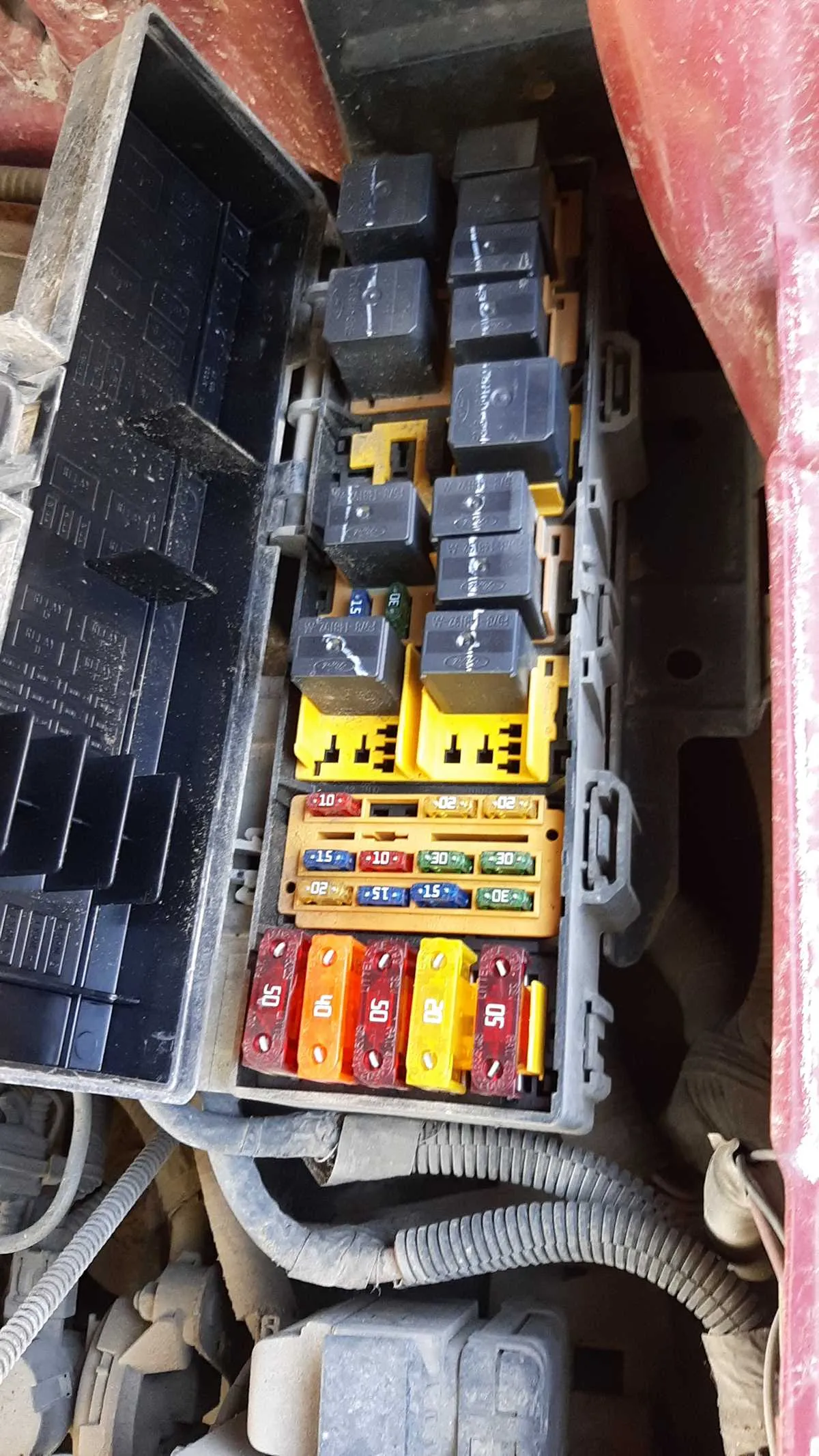
If you’re troubleshooting issues with your car’s electrical components, begin by checking the distribution box, which contains the main relays and connections. This component is crucial for ensuring the proper functioning of critical systems like lights, wipers, and the ignition. Knowing the exact location of each fuse will save time when diagnosing or replacing faulty circuits.
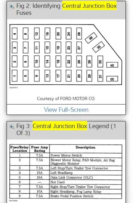
To locate the correct fuses for specific functions, refer to the reference chart found in the vehicle’s manual. This chart will show you which fuse controls each system, such as air conditioning, lights, or the engine control unit. For quick identification, use a diagram to match the fuses with the corresponding systems, ensuring you replace them accurately.
Keep in mind, a quick visual inspection of the distribution box is often enough to identify blown fuses. If you’re unsure, use a multimeter to check continuity across each fuse to confirm whether it’s functioning. Always replace any damaged components with the correct amperage ratings to avoid further electrical problems.
For those more familiar with automotive repairs, knowing how to reset or replace the distribution box can save you significant labor costs. Make sure to disconnect the vehicle’s battery before attempting any repair or inspection. Lastly, keep a spare set of fuses in your toolbox; they’re compact and can easily prevent delays during emergencies.
Electrical System Layout and Troubleshooting
For accurate identification of the electrical circuits in your vehicle, it is essential to refer to the location and configuration of the central power distribution box. This will help you locate specific connections for critical components like the ignition system, lighting, and entertainment features.
Key Points to Consider:
- Inspect the main relay box under the dashboard or engine compartment for proper labels and color-coded components.
- Ensure that each connection is intact and no wires are frayed or exposed to prevent short circuits.
- If a malfunction occurs, check the respective fuse slot for damage or signs of burning, which may indicate overload or faulty circuitry.
In case of electrical issues, begin by turning off all accessories before checking the related connections. Use a multimeter to test for continuity in the affected components. If you are unfamiliar with the wiring layout, consult the vehicle’s user manual for detailed explanations and reference points.
Remember: Always replace any damaged components with the correct amperage ratings to maintain safety and prevent further electrical damage. Regular maintenance and checks will ensure smooth operation of your vehicle’s electrical systems.
Locating the Electrical Junction in Your Pickup
To access the main electrical control unit in your truck, start by opening the driver’s side door. The compartment is typically located beneath the dashboard, near the left side. You may need to remove a cover or panel to reveal the components inside.
Another common location is under the hood. Look for a rectangular box near the engine bay, often situated next to the battery. This area houses the high-power relays and connectors that manage engine and exterior functions.
If you have difficulty locating the unit, check your vehicle’s manual for detailed instructions specific to your model year.
Understanding the Fuse Layout and Functions
Start by checking the index inside the cabin’s relay box cover–this will guide you directly to the correct slot for each component. Pay close attention to the amperage ratings; inserting a higher-rated element can cause serious electrical damage.
Slot 1 typically controls the low beam on the driver’s side. If your headlamp isn’t working, inspect this position first. Slot 2 often powers the passenger-side low beam. Slot 10 might be dedicated to the radio or infotainment system–pulling this unit can reset audio functions if needed.
Use a multimeter to verify voltage continuity rather than relying solely on visual inspection. Blown units may appear intact. Refer to the power distribution box near the engine compartment for higher-draw components like the cooling fan or ABS system.
Replace only with the exact amperage marked; never improvise. This ensures circuit protection and prevents wire overheating or component failure.
Troubleshooting Common Electrical Interruptions

Begin by checking the power distribution box under the hood using a test light or multimeter. Locate the affected circuit, referencing the lid chart for slot assignments.
- Loss of interior lighting: Inspect position 27 (10A) and verify continuity.
- Non-functional radio or infotainment: Examine cavity 15 (15A) and confirm voltage input with ignition on.
- Blower motor not working: Review terminal 23 (30A) and check associated relay for audible click on startup.
When the issue persists despite an intact filament, perform a voltage drop test across both terminals with the accessory activated. Absence of 12V likely indicates corrosion at the socket or a damaged wire upstream.
- Disconnect the battery before removal to avoid shorts.
- Use needle-nose pliers for stubborn inserts, but avoid bending prongs.
- Replace only with the same amperage rating; higher ratings may cause overheating or fire.
For recurring blowouts, isolate the component by unplugging downstream loads one at a time. Pay attention to aftermarket accessories tied into the same circuit, which often lack proper grounding or draw excessive current.