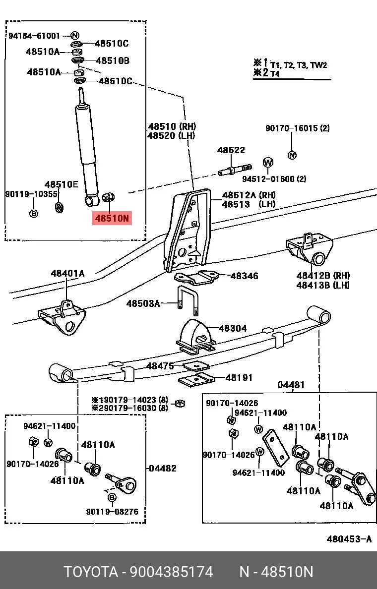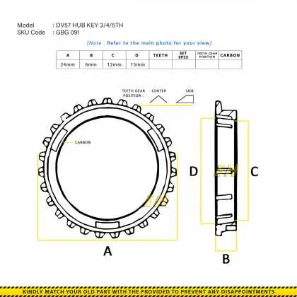
When working with mechanical equipment, understanding the intricate details of its assembly is crucial for smooth operation and long-term reliability. Make sure to reference a detailed component map to correctly identify each part’s role within the system. This will help ensure proper maintenance and replacement of worn or damaged items.
For users of this specific model, precise identification of individual elements is essential for troubleshooting and repairs. Utilize available resources that provide detailed schematics to guide disassembly and reassembly processes. These illustrations show exact part placements and provide key insights into the interaction between different sections of the unit.
Ensure that you have access to the correct blueprint that corresponds to your particular system version. Misinterpreting the layout can lead to improper fixes, causing further issues down the line. Having the right documentation at hand saves time and minimizes errors during routine servicing.
In addition to referring to the schematic for part identification, also make use of the recommended specifications for each part’s compatibility with other components. This prevents mismatched or suboptimal replacements that could compromise the functionality of your machine.
Repair and Maintenance Overview for the DM950GFI Engine Model
For effective maintenance and repair, always refer to the technical blueprint when dealing with components of the DM950GFI engine model. Each part is numbered for easy identification and ensures proper alignment during reassembly.
Ensure you have the right tools for disassembly, especially for the smaller fasteners. A torque wrench is essential to tighten components to manufacturer specifications, preventing over-tightening or under-tightening, which can lead to damage or inefficient performance.
For the fuel system, ensure the correct seals and gaskets are used during assembly to avoid leaks. Pay close attention to the fuel filter’s location, and replace it regularly to maintain engine efficiency. The ignition system requires periodic inspection of spark plugs and wires for any signs of wear or corrosion. Ensure these components are replaced according to the recommended intervals.
Regarding the cooling system, check hoses for cracks or signs of wear. The coolant pump and thermostat should be inspected regularly to ensure the engine operates within the optimal temperature range. Replace the coolant based on the maintenance schedule to prevent overheating and related damage.
The exhaust system components, including the manifold and pipes, should be checked for leaks. Any rust or cracks should be addressed promptly to prevent emission issues and engine inefficiency.
Keep the air intake and exhaust valves clean and free from carbon build-up to maintain engine performance. When working on the timing belt or chain, ensure they are properly aligned before reassembly, as improper installation can lead to engine misfires or even serious damage.
Understanding the Core Components of the DM950GFI Engine
For optimal engine performance, focus on the essential components that drive its efficiency and reliability. Key elements include the fuel system, ignition system, lubrication system, and cooling system. Each part plays a critical role in ensuring smooth operation, minimal wear, and enhanced fuel efficiency.
Fuel System: The carburetor or fuel injection system regulates fuel delivery to the combustion chamber. Pay attention to the fuel filter’s condition, as it prevents contaminants from entering the engine. Regular maintenance of this system ensures consistent power output and prevents engine misfires.
Ignition System: The spark plug and ignition coil are fundamental for creating the electrical arc needed to ignite the air-fuel mixture. A worn spark plug can cause inefficient combustion, leading to poor performance. Periodically inspect the plugs and replace them when necessary to maintain optimal firing timing.
Lubrication System: The oil pump circulates oil to reduce friction between moving parts, while the oil filter captures debris. Ensure that the oil is at the recommended level and change it based on manufacturer guidelines to avoid overheating or excessive wear.
Cooling System: The cooling system, often involving a radiator and water pump, prevents the engine from overheating. If you notice a decrease in coolant levels or signs of leakage, address these issues promptly to avoid potential engine damage.
Keeping these components in top condition will result in greater efficiency, longer engine life, and smoother operation. Regular inspection and timely replacements are essential for maintaining peak performance over time.
How to Locate and Identify Specific Components in the Schematic
Start by referencing the key index or part list provided in the schematic. This will typically include a number associated with each element, allowing you to cross-check the part against its description. If the schematic is divided into sections, focus on the area most relevant to the component you’re looking for, as this can significantly narrow down your search.
Next, use the part’s unique identifier, such as a code or label, to pinpoint its exact location on the visual representation. Compare the label on the part with the references in the schematic. Pay attention to any color coding or specific markers that could highlight particular components, as these can further assist in differentiation.
If you’re uncertain, follow the lines or connections between parts. These visual cues often lead to a more accurate identification. Additionally, some schematics include dimensional labels or scale indicators, which can help verify the size and placement of the component you’re investigating.
When the part is located, note its relationship to other components. Understanding how it interacts with surrounding elements can clarify its function and confirm its identity. If multiple options are shown for a specific part, review any accompanying notes to determine the correct variant for your particular model or configuration.
Step-by-Step Guide to Replacing Faulty Components Using the Blueprint

Start by identifying the malfunctioning component in your system. Use the reference chart to locate the exact part and its position within the assembly.
- Gather the necessary tools: screwdriver, wrenches, pliers, and any other equipment specified for the task.
- Disconnect the power supply to avoid any accidents during the replacement process.
- Remove the cover or housing protecting the faulty unit. Follow the guide to ensure you don’t damage surrounding parts.
- Use the reference chart to confirm the identification of the damaged item. Note the part number for compatibility with the new one.
- Carefully detach the defective component. Depending on the model, this may involve loosening screws or disconnecting wiring.
- Place the new component in its correct position. Ensure it aligns with the mounting points outlined in the schematic.
- Reattach any wiring or connectors. Double-check for a secure fit to prevent issues later.
- Tighten all screws and fasteners to the manufacturer’s specifications.
- Test the unit to ensure the new part is functioning as expected. If applicable, run diagnostic checks to confirm proper operation.
Repeat this process for each faulty item within the assembly. Make sure to follow each step carefully for a successful replacement.